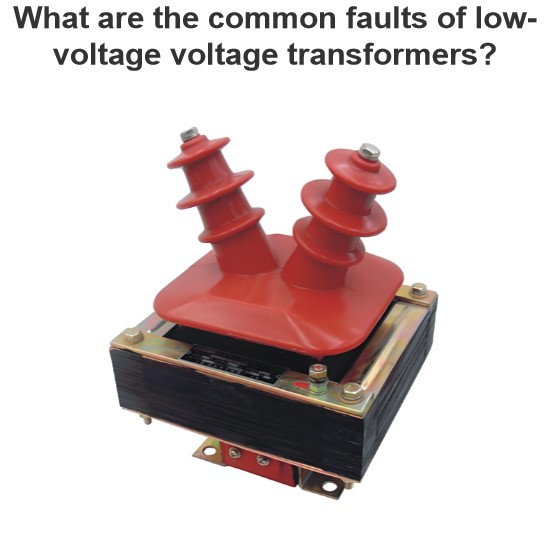
Low-voltage current transformers, as indispensable measurement and protection devices in power systems, often encounter various faults when used in combination with other power equipment due to environmental factors, equipment linkage issues, and improper installation and maintenance. These faults not only affect the normal operation of power equipment but may also endanger personal safety. Therefore, it is necessary to gain an in-depth understanding of fault types, judgment methods, and preventive measures to ensure the stable and reliable operation of rural power grids and low-voltage distribution systems.
I. Typical Connection Scenarios of Low-voltage Current Transformers with Other Power Equipment
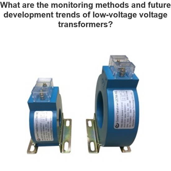
Low-voltage current transformers are mainly used in connection with the following equipment in power systems, forming different application scenarios:
- Electric energy metering systems: Connected with metering instruments such as watt-hour meters and power meters to accurately measure users' electricity consumption. In rural power grids, they are commonly found in farmers' meter boxes or on the low-voltage side of distribution transformers, responsible for converting large currents into standard small current signals of 5A or 1A for metering purposes.
- Relay protection devices: Connected with protective devices such as circuit breakers, residual current protectors, and overload protectors to monitor line current status and cut off fault currents in a timely manner. In rural distribution boxes, they are often used to monitor line overload, short circuits, or leakage.
- Automation control systems: Connected with automation equipment such as PLCs and RTUs for remote monitoring and control of the operating status of power equipment. They are common in rural small processing plants, irrigation pumping stations, and other places.
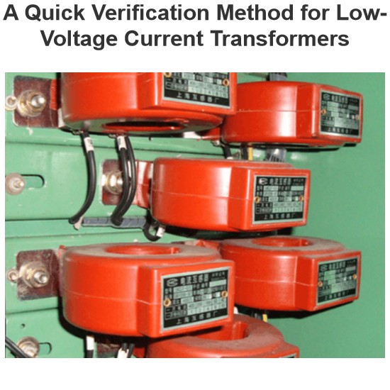
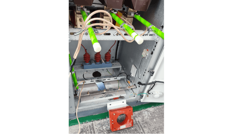
- Distribution transformers: Connected with the outgoing lines on the low-voltage side of transformers to monitor the operating status and load conditions of transformers. They are commonly found at the outgoing lines on the low-voltage side of rural distribution transformers.
II. Common Faults When Low-voltage Current Transformers Are Used in Combination with Other Power Equipment
1. Open Circuit Fault in Secondary Circuit
An open circuit in the secondary circuit is one of the most dangerous faults of low-voltage current transformers, mainly characterized by:
- Phenomenal features: The indication of ammeters and power meters suddenly becomes zero or fluctuates significantly; the transformer body makes an abnormal "buzzing" sound or discharge sound; there are visible burnt marks at the terminal block; the watt-hour meter stops rotating or rotates abnormally.
- Causes of failure: Loose terminals in the secondary circuit; broken secondary wires during meter installation; accidental disconnection of the secondary circuit during maintenance; poor contact due to oxidation of the terminal block; mechanical damage to the secondary wires causing breakage.
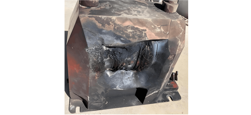
- Hazards of failure: When open-circuited, the secondary side will generate a high voltage of several thousand volts, threatening the safety of operators; severe saturation of the iron core leads to overheating, which may burn insulation materials; protection devices malfunction or fail to operate due to signal loss.
Typical rural scenario case: In a village transformer area, the secondary wires of the current transformer in the meter box became loose at the terminals due to long-term vibration. When farmers used high-power electrical appliances, an open circuit in the secondary circuit generated high voltage, causing the meter to burn out and creating a fire hazard.
2. Poor Contact Fault
Poor contact is one of the most common faults when low-voltage current transformers are connected with other equipment:
- Phenomenal features: Unstable ammeter indication, intermittent presence; abnormal temperature rise at the transformer terminals; frequent misoperation of protection devices; increased metering errors; visible oxidation and blackening at the terminal block.
- Causes of failure: Loose screws on the terminal block; insufficient contact area between wires and terminals; oxidation or corrosion of wires; aging of terminal block materials; non-compliant bolt torque; increased contact resistance accelerated by a humid environment.
- Hazards of failure: Increased contact resistance leads to local overheating, accelerating insulation aging; increased measurement errors affect metering accuracy; protection devices malfunction or fail to operate due to abnormal signals; long-term poor contact may cause short circuits or fires.
Typical rural scenario data: In a metering circuit connected with 2.5mm² copper wires, when the contact resistance exceeds 0.65mΩ, the terminal temperature rise can reach more than 40℃; when the contact resistance exceeds 1mΩ, the temperature rise can reach more than 70℃, far exceeding the safety limit.
3. Overload and Iron Core Saturation Faults
Overload and iron core saturation are common fault types in rural power grids, mainly characterized by:
- Phenomenal features: Ammeter indication exceeds the rated value; the transformer body heats up significantly; protection devices malfunction or fail to operate; increased metering errors; abnormal noise from the iron core.
- Causes of failure: Large fluctuations in rural grid loads (such as peak electricity consumption during the Spring Festival and multiple water pumps operating simultaneously during the irrigation season) cause the transformer to work in an overload state for a long time; improper selection of the accuracy limit factor of the transformer; short-circuit current exceeding the bearing capacity of the transformer; degradation of iron core material performance; reduced magnetic permeability due to temperature rise.
- Hazards of failure: Iron core saturation leads to increased measurement errors, affecting metering accuracy; protection devices malfunction or fail to operate due to signal distortion; reduced insulation performance of the transformer; long-term overload may burn the transformer.
Typical rural scenario data: The current transformer on the low-voltage side of a rural distribution transformer reached 120% of the rated current during the summer irrigation period, causing iron core saturation, a measurement error of 8%, and a 3-fold increase in the number of misoperations of protection devices.
4. Insulation Performance Degradation Fault
Insulation faults are particularly prominent in rural power grids, mainly characterized by:
- Phenomenal features: Reduced insulation resistance (should be ≥1000MΩ under normal conditions); partial discharge phenomenon; surface discharge marks; increased leakage current; dampness or water stains on the equipment surface.
- Causes of failure: Humid rural environments and poor sealing of the transformer leading to water ingress; insulation damage caused by gnawing of small animals; accelerated insulation aging due to long-term high-temperature operation; reduced insulation performance due to dust accumulation on the terminal block; insulation breakdown caused by lightning overvoltage.
- Hazards of failure: Degraded insulation performance leads to leakage or short circuits; misoperation of protection devices; increased metering errors; and may even cause fires in severe cases.
Typical rural scenario data: In southern rural areas, the humidity is maintained above 80% all year round. The insulation resistance of transformers without moisture-proof measures may drop from the initial value of 2000MΩ to below 500MΩ within 2-3 years.
III. Judgment Methods for Common Faults
1. Judgment of Open Circuit Fault in Secondary Circuit
- Meter observation method: Check whether the indication of connected ammeters and power meters suddenly becomes zero or fluctuates significantly; whether the watt-hour meter stops rotating or rotates abnormally.
- Sound identification method: Approach the transformer body and listen for abnormal "buzzing" or discharge sounds; the sound should be small and uniform during normal operation.
- Temperature detection method: Use an infrared thermometer to detect the temperature of the transformer body, which should be ≤40℃ under normal conditions; it may reach above 60℃ when open-circuited.
- Impedance testing method: Use a special instrument to measure the impedance of the secondary circuit. The impedance angle is independent of frequency when connected normally; the impedance increases significantly (>10000Ω) when open-circuited.
Rural scenario judgment skill: In rural low-voltage metering boxes, if it is found that the electric meter suddenly stops working while farmers' electricity usage is normal, the secondary circuit of the current transformer should first be suspected of being open-circuited.
2. Judgment of Poor Contact Fault
- Loop resistance testing method: Use a micro-ohmmeter to measure the secondary circuit resistance, which should be ≤0.65mΩ under normal conditions; the resistance may exceed 1mΩ when there is poor contact.
- Temperature rise monitoring method: Use an infrared thermometer to monitor the temperature rise of the terminal block, which should be ≤15℃ under normal conditions; the temperature rise may exceed 30℃ when there is poor contact.
- Vibration detection method: Use a vibration sensor to detect abnormal vibrations. When there is poor contact, the vibration amplitude may exceed 2g and last for more than 10 seconds.
- Load testing method: Connect a standard load to the secondary circuit of the transformer and observe whether the output current is stable; the current may fluctuate when there is poor contact.
Rural scenario judgment skill: In metering boxes after rural network centralized reading transformation, if it is found that the metering of a certain household's electric meter is abnormal while that of other households is normal, focus should be on checking the connection status of the secondary circuit of the current transformer for that household.
3. Judgment of Overload and Iron Core Saturation Faults
- Current monitoring method: Check whether the actual load current on the primary side exceeds the rated value; special attention should be paid to peak electricity consumption periods in rural power grids, such as the Spring Festival and the irrigation season.
- Error testing method: Use a transformer calibrator to test the ratio error and phase error, which should meet the accuracy level requirements under normal conditions; errors may increase significantly during overload or saturation.
- Excitation characteristic testing: Measure the secondary voltage under different currents and draw the excitation curve; the slope of the curve will change significantly when the iron core is saturated.
- Sound identification method: The iron core may make abnormal noise when saturated; the sound should be small and uniform during normal operation.
Rural scenario judgment skill: On the low-voltage side of rural distribution transformers, if it is found that protection devices frequently malfunction when multiple high-power electrical appliances are operating simultaneously, the current transformer should be suspected of being overloaded or having iron core saturation.
4. Judgment of Insulation Performance Degradation Fault
- Insulation resistance testing method: Use a 2500V megohmmeter to measure the insulation resistance between the primary and secondary, secondary to ground, and primary to ground; it should be ≥1000MΩ under normal conditions.
- Partial discharge testing method: Use a partial discharge tester to detect internal discharge in the transformer; the discharge amount will increase when insulation performance degrades.
- Visual inspection method: Check whether there are water stains, dirt, or damage on the transformer surface; whether there is dust accumulation or signs of animal gnawing on the terminal block.
- Humidity detection method: Use a hygrometer to detect the humidity of the transformer installation environment; a humid environment in rural areas may lead to degradation of insulation performance.
Rural scenario judgment skill: In southern rural areas, if it is found that the insulation resistance of the transformer has decreased significantly, focus should be on checking whether the sealing structure is intact and whether the environmental humidity is too high.
IV. Solutions to Common Faults
1. Handling of Open Circuit Fault in Secondary Circuit
- Emergency treatment: After discovering an open circuit fault, immediately deactivate the relevant protection devices; use insulating tools to short-circuit the secondary side at the terminals near the transformer; if there is a spark during short-circuiting, it indicates that the fault point is in the circuit below the short-circuit point; if there is no spark during short-circuiting, the fault point may be in the circuit before the short-circuit point.
- Long-term solutions: Replace the secondary wiring terminals with reliable quality; use gold-plated or tinned terminal materials to reduce oxidation; install anti-loosening gaskets or Snap-on limiters to prevent vibration-induced loosening; regularly check the connection status of the secondary circuit.
Rural scenario handling suggestions: In rural low-voltage metering boxes, secondary circuit short-circuit protection devices can be installed to automatically short-circuit when an open circuit is detected; regular inspections should be conducted by electricians, especially before peak electricity consumption periods.
2. Handling of Poor Contact Fault
- Maintenance measures: Use a torque wrench to tighten terminal screws according to specifications (such as 0.8-1.2N·m for M4 screws); regularly clean the oxide layer on terminals; apply conductive paste to terminal contact surfaces; inspect and replace aging or damaged terminal blocks.
- Preventive measures: Install moisture-proof heaters at terminal block connections (automatically start when humidity >60% RH); use G4-grade filter cotton to block dust (replace every 6 months); adopt metering boxes with IP65 protection level; regularly inspect and maintain terminal blocks.
Rural scenario handling suggestions: In rural network metering boxes, gold-plated or tinned terminal materials can be used; shockproof terminal blocks can be adopted; terminal connection status should be checked once a quarter; the inspection frequency should be increased during the humid season.
3. Handling of Overload and Iron Core Saturation Faults
- Protection configuration: Select transformers with appropriate transformation ratios according to the actual line load; protection current transformers should select appropriate accuracy limit factors (such as 10P15 can withstand 15 times the rated current); configure residual current circuit breakers matching the cross-sectional area of the wires at the incoming line (such as 2.5mm² copper wires with C20A protectors) .
- Selection suggestions: Select transformers with a rated secondary current of 1A or 5A according to line length and load conditions; 1A transformers are suitable for long-distance metering; in rural power grids, iron core materials with good anti-saturation performance (such as permalloy) can be selected.
Rural scenario handling suggestions: At the incoming lines of farmers' homes, select appropriate protection devices according to the wire diameter (such as 1.5mm² copper wires with C10A, 2.5mm² with C20A, 4mm² with C25A); on the low-voltage side of distribution transformers, reserve sufficient transformer capacity according to load conditions; adopt intelligent monitoring devices to monitor the operating status of transformers in real-time.
4. Handling of Insulation Performance Degradation Fault
- Maintenance measures: Regularly check whether the sealing structure of the transformer is intact; use silicone rubber sealing rings to enhance sealing; install moisture-proof heaters in metering boxes; clean dirt on the transformer surface.
- Preventive measures: Select metering boxes with IP65 protection level; use flame-retardant ABS materials for the shell; use moisture-proof wiring terminals at the terminal block; conduct regular insulation resistance tests.
Rural scenario handling suggestions: In southern rural areas, epoxy resin-cast transformers can be adopted; install temperature and humidity monitoring devices in metering boxes; regularly inspect and replace aging sealing materials; install lightning arresters in lightning-prone areas.