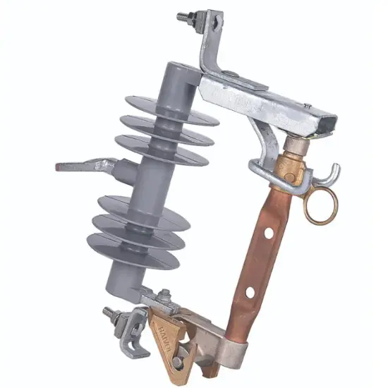
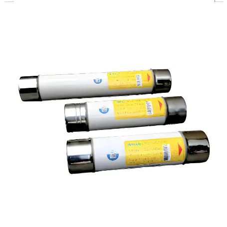
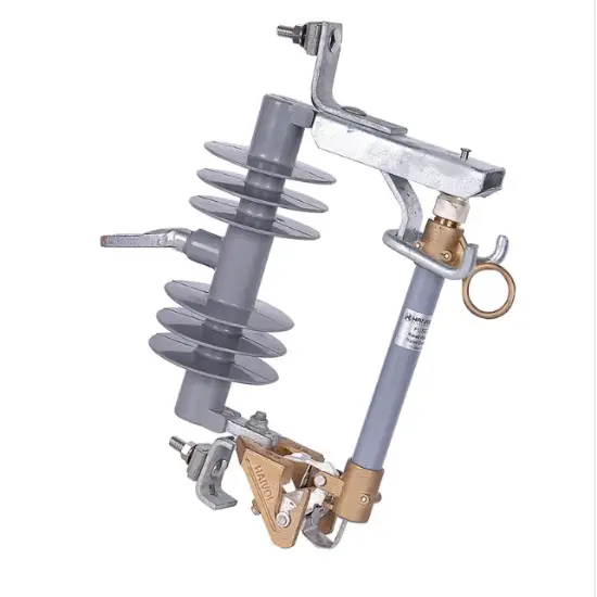
• Product
  • Suppliers
  • Manufacturers
  • Solutions
  • Free tools
  • Knowledges
  • Experts
  • Communities
Search


DNS – M1L series aR Semiconductor

  • DNS – M1L series aR Semiconductor
  • DNS – M1L series aR Semiconductor

Key attributes

Brand Switchgear parts
Model NO. DNS – M1L series aR Semiconductor
Rated voltage DC 800V
Rated normal current 700-800A
Breaking capacity 50kA
Series DNS – M1L

Product descriptions from the supplier

Description

What are the latest innovations in semiconductor fuse technology?

 The semiconductor fuse technology had been evolving with several innovations aimed at enhancing performance, reliability, and application-specific functionalities. These advancements reflect the growing demands of modern electronic and electrical systems, particularly in industries like renewable energy, electric vehicles, and high-speed computing. Here are some of the latest innovations in semiconductor fuse technology:

Enhanced Materials

High-Performance Conductive Materials: Research and development in advanced conductive materials, including composites and alloys, have led to fuses with better conductivity, lower heat generation, and improved overall efficiency.

Improved Arc-Quenching Materials: Innovations in arc-quenching materials help in quicker and safer interruption of overcurrents, especially critical in high-voltage DC applications like electric vehicles and renewable energy systems.

Miniaturization

Compact Designs: With the trend of miniaturization in electronics, fuses are becoming smaller while still maintaining or even increasing their current and voltage handling capabilities. This is particularly important in applications like consumer electronics and IoT devices.

Surface-Mount Technology (SMT) Fuses: Advances in SMT fuses allow for direct mounting on PCBs, saving space and improving performance in compact electronic devices.

Smart Fuses

Integration with Sensors and IoT: Some semiconductor fuses are now being integrated with sensors that can provide real-time data on current, voltage, and temperature. This data can be used for predictive maintenance and to improve system reliability.

Communication Capabilities: Fuses with built-in communication capabilities can interface with control systems or IoT networks, enabling remote monitoring and control.

Application-Specific Innovations

EV-Specific Fuses: With the rise of electric vehicles, there’s been a focus on developing fuses that can handle high voltages and currents, rapid charge/discharge cycles, and are resistant to vibration and thermal cycling.

Renewable Energy Fuses: Fuses designed specifically for solar panels, wind turbines, and battery storage systems, capable of handling unique challenges like fluctuating current levels and environmental exposure.

Improved Safety Features

Blow-Indicator Fuses: These fuses include an indicator pin or flag that pops up when the fuse blows, making it easier to identify and replace blown fuses, crucial in complex systems with multiple fuses.

Non-Explosive Designs: For high-power applications, fuses are being designed to operate without explosive rupture under fault conditions, enhancing safety.

Environmental Sustainability

Eco-Friendly Materials: The use of lead-free and other environmentally friendly materials in fuse manufacturing is growing, driven by regulations and sustainability goals.

Recyclability: There’s an increasing focus on making fuses more recyclable, in line with global trends towards reducing electronic waste.

Conclusion

The semiconductor fuse industry is continually innovating to meet the evolving needs of modern technology and infrastructure. These advancements not only aim at improving electrical performance and safety but also at ensuring compatibility with the latest trends in electronics design and sustainable practices. As technology continues to advance, we can expect to see further innovations in this field, particularly in areas like smart functionality, materials science, and application-specific design.

Basic parameters of fuse links

Product model Rated voltage          V Rated current         A Rated breaking  capacity    kA
DNS20-M1L-35 DC  800 35 50
DNS20-M1L-40   40  
DNS20-M1L-50   50  
DNS20-M1L-63   63  
DNS24-M1L-70   70  
DNS24-M1L-80   80  
DNS24-M1L-90   90  
DNS24-M1L-100   100  
DNS38-M1L-125   125  
DNS38-M1L-160   160  
DNS38-M1L-170   170  
DNS38-M1L-200   200  
DNS51-M1L-225   225  
DNS51-M1L-250   250  
DNS51-M1L-315   315  
DNS51-M1L-350   350  
DNS51-M1L-400   400  
DNS64-M1L-425   425  
DNS64-M1L-450   450  
DNS64-M1L-500   500  
DNS64-M1L-550   550  
DNS64-M1L-600   600  
DNS51-M1L-700   700  
DNS51-M1L-750   750  
DNS51-M1L-800   800
Know your supplier
Online store
On-time delivery rate
Response time
100.0%
≤4h
Company overview
Workplace: 1000m² Total staff: Highest Annual Export(usD): 300000000
Workplace: 1000m²
Total staff:
Highest Annual Export(usD): 300000000
Services
Business Type: Sales
Main Categories: Low Voltage Electrical Apparatus/Instrument meters/Production equipment/Tester/High Voltage Electrical Apparatus/Electrical fittings/Equipment Parts
Whole life care manager
Whole-life care management services for equipment procurement, use, maintenance, and after-sales, ensuring safe operation of electrical equipment, continuous control, and worry-free electricity consumption.
The equipment supplier has passed platform qualification certification and technical evaluation, ensuring compliance, professionalism, and reliability from the source.

Related Products

Related Knowledges

  • Impact of DC Bias in Transformers at Renewable Energy Stations Near UHVDC Grounding Electrodes
    Impact of DC Bias in Transformers at Renewable Energy Stations Near UHVDC Grounding ElectrodesWhen the grounding electrode of an Ultra-High-Voltage Direct Current (UHVDC) transmission system is located close to a renewable energy power station, the return current flowing through the earth can cause a rise in ground potential around the electrode area. This ground potential rise leads to a shift in the neutral-point potential of nearby power transformers, inducing DC bias (or DC offset) in their
    01/15/2026
  • HECI GCB for Generators – Fast SF6 Circuit Breaker
    1.Definition and Function1.1 Role of the Generator Circuit BreakerThe Generator Circuit Breaker (GCB) is a controllable disconnect point located between the generator and the step-up transformer, serving as an interface between the generator and the power grid. Its primary functions include isolating generator-side faults and enabling operational control during generator synchronization and grid connection. The operating principle of a GCB is not significantly different from that of a standard c
    01/06/2026
  • Distribution Equipment Transformer Testing, Inspection, and Maintenance
    1.Transformer Maintenance and Inspection Open the low-voltage (LV) circuit breaker of the transformer under maintenance, remove the control power fuse, and hang a “Do Not Close” warning sign on the switch handle. Open the high-voltage (HV) circuit breaker of the transformer under maintenance, close the grounding switch, fully discharge the transformer, lock the HV switchgear, and hang a “Do Not Close” warning sign on the switch handle. For dry-type transformer maintenance: first clean the porcel
    12/25/2025
  • How to Test Insulation Resistance of Distribution Transformers
    In practical work, insulation resistance of distribution transformers is generally measured twice: the insulation resistance between thehigh-voltage (HV) windingand thelow-voltage (LV) winding plus the transformer tank, and the insulation resistance between theLV windingand theHV winding plus the transformer tank.If both measurements yield acceptable values, it indicates that the insulation among the HV winding, LV winding, and transformer tank is qualified. If either measurement fails, pairwise
    12/25/2025
  • Design Principles for Pole-Mounted Distribution Transformers
    Design Principles for Pole-Mounted Distribution Transformers(1) Location and Layout PrinciplesPole-mounted transformer platforms should be located near the load center or close to critical loads, following the principle of “small capacity, multiple locations” to facilitate equipment replacement and maintenance. For residential power supply, three-phase transformers may be installed nearby based on current demand and future growth projections.(2) Capacity Selection for Three-Phase Pole-Mounted Tr
    12/25/2025
  • Transformer Noise Control Solutions for Different Installations
    1.Noise Mitigation for Ground-Level Independent Transformer RoomsMitigation Strategy:First, conduct a power-off inspection and maintenance of the transformer, including replacing aged insulating oil, checking and tightening all fasteners, and cleaning dust from the unit.Second, reinforce the transformer foundation or install vibration isolation devices—such as rubber pads or spring isolators—selected based on the severity of vibration.Finally, strengthen sound insulation at weak points of the ro
    12/25/2025
Haven't found the right supplier yet? Let matching verified suppliers find you. Get Quotation Now
Haven't found the right supplier yet? Let matching verified suppliers find you.
Get Quotation Now
Send inquiry
+86
Click to upload file

IEE Business will not sell or share your personal information.

Download
Get the IEE Business Application
Use the IEE-Business app to find equipment, obtain solutions, connect with experts, and participate in industry collaboration anytime, anywhere—fully supporting the development of your power projects and business.