
| Brand | Wone |
| Model NO. | 1kW / 1.036 kWh portable power station |
| 输出功率 | 1000W |
| Energy capacity | 1036Wh |
| Series | Portable power station |
Description:
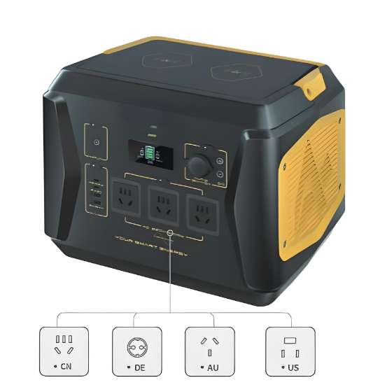
This 1kW / 1.036 kWh portable power station can support up to 12 devices simultaneously, is easy to carry (11kg), and ideal for outdoor activities as well as emergency power supply for homes. This is a lifestyle change-maker and the dream device for adventurers.
Feature:
3- Level Brightness.
SOS Function.
Equipped with 2 Wireless Charging Pads.
Capable to Charge 12 Devices Simultaneously.
Big Capacity in Small Box.
Basic parameters:

Electrical Parameters:

How are portable charging stations overcharged protected?
Voltage Detection:
Function: The Battery Management System (BMS) continuously monitors the voltage of each battery cell.
Principle: When the voltage of a battery cell reaches or approaches the preset upper limit (for example, the upper limit of a lithium-ion battery is usually 4.2V), the BMS will trigger overcharge protection.
Current Detection:
Function: The BMS monitors the charging current.
Principle: If the charging current exceeds the preset safety threshold, the BMS will reduce the charging current or completely cut off the charging circuit.
Temperature Detection:
Function: The BMS monitors the temperature of the battery.
Principle: If the battery temperature exceeds the preset safety threshold (for example, 60°C), the BMS will reduce the charging current or completely cut off the charging circuit to prevent dangers caused by overheating.
Logic Control:
Function: The BMS makes logical judgments based on the data of voltage, current, and temperature to decide whether to activate overcharge protection.
Principle: The microprocessor built into the BMS will judge whether the battery is in an overcharged state according to the preset algorithms and thresholds. If overcharge conditions are detected, the BMS will execute corresponding protection measures.
Protection Measures:
Cutting off the Charging Circuit: The BMS cuts off the charging circuit by controlling the charging relay or MOSFET (Metal Oxide Semiconductor Field Effect Transistor) to prevent the current from continuing to flow into the battery.Reducing the Charging Current: In some cases, the BMS may first reduce the charging current to observe the changes in the battery state. If the battery voltage still rises, then the charging circuit will be completely cut off.
Alarm Notification: The BMS can issue an alarm through the display screen or indicator light to remind the user that the battery has reached a full charge state and the charger needs to be disconnected.

-
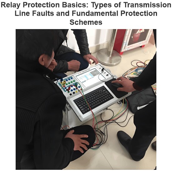 Relay Protection Basics: Types of Transmission Line Faults and Fundamental Protection Schemes1. Types of Faults on Power LinesPhase-to-Phase Faults: Three-phase short circuit Two-phase short circuitGround Faults: Single-phase to ground fault Two-phase to ground fault Three-phase to ground fault2. Definition of Relay Protection DevicesWhen an abnormality or fault occurs in a component of a power system, relay protection devices are those that can quickly and selectively isolate the faulty or abnormal component from the system, ensuring the continued normal operation of the remaining healLeon09/05/2025
 -
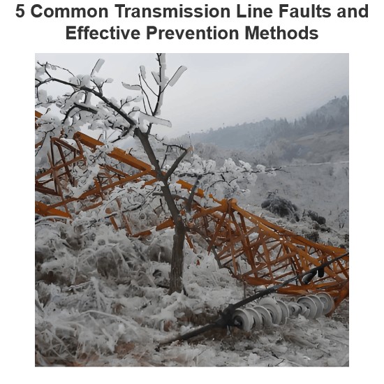 5 Common Transmission Line Faults and Effective Prevention Methods1. OverviewA transmission line fault is a sudden power interruption caused by various factors. To restore supply and prevent recurrence, operators must first locate the fault point, identify the type, determine the cause, and implement repairs.The most common faults include: Lightning strikes Ice buildup (icing) Wind deviation (wind sway) Bird-related issues Pollution flashover External damageUnderstanding these faults and their prevention is critical for grid reliability.2. Lightning Strike FauEdwiin09/05/2025
 -
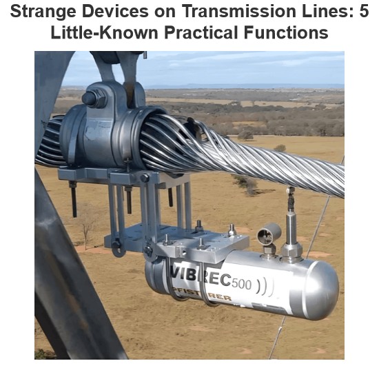 Strange Devices on Transmission Lines: 5 Little-Known Practical Functions(1)1 Aviation Warning SpheresAviation warning spheres, also known as reflective safety spheres, are used on overhead transmission lines near airports, especially on extra-high-voltage (above 220kV) lines and river-crossing transmission lines. Highly visible aviation marker spheres (aviation warning spheres) must be installed along the lines to provide warning signals.The aviation marker sphere (aviation warning sphere) has a diameter of ф=600mm. The sphere can be manufactured in various bright coloLeon09/04/2025
 -
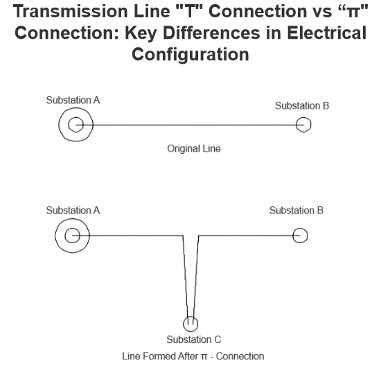 Transmission LineIn transmission lines, a "π" connection involves breaking the original line from Substation A to Substation B and inserting Substation C, forming a "π" configuration. After the "π" connection, the original single line is divided into two independent transmission lines. Following the "π" connection, Substations B and C may both be powered by Substation A (in this case, Substation C receives power via a feeder from Substation B's busbar, or possibly from another voltage point within Substation B);Encyclopedia09/04/2025
 -
 What are the principles of forced re-energization of transmission lines?Principles of Forced Re-energization of Transmission LinesRegulations for Forced Re-energization of Transmission Lines Correctly select the forced re-energization end of the line. If necessary, change the connection configuration before forced re-energization, taking into account the reduction of short-circuit capacity and its impact on grid stability. There must be a transformer with its neutral point directly grounded on the busbar at the forced re-energization end. Pay attention to the impactEdwiin09/04/2025
 -
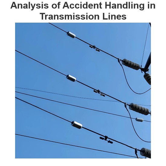 Analysis of Accident Handling in Transmission LinesAnalysis of Transmission Line Fault HandlingAs a fundamental component of the power grid, transmission lines are widely distributed and numerous, often exposed to diverse geographical and climatic conditions, making them highly susceptible to faults. Common causes include overvoltage, pollution flashover, insulation damage, tree encroachment, and external damage. Line tripping is one of the most frequent faults in power plant and substation operations, with fault types including single-phase-to-Leon09/04/2025


