• Product
  • Suppliers
  • Manufacturers
  • Solutions
  • Free tools
  • Knowledges
  • Experts
  • Communities
Search


6kV 10kV High-voltage starting reactor with F Insulation Class

  • 6kV 10kV High-voltage starting reactor with F Insulation Class

Key attributes

Brand POWERTECH
Model NO. High-voltage starting reactor
Starting current 142A
Starting capacity 520KVar
Series QKSG

Product descriptions from the supplier

Description

Description:

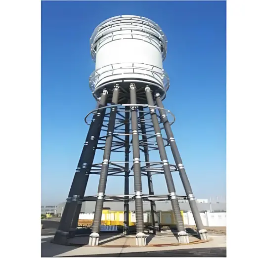
When the AC asynchronous motor is started at the rated voltage, the initial starting current is very large, often exceeding many times of the rated current (generally 5~7 times). In order to reduce the starting current and not affect the power grid, the AC asynchronous motor is usually started by reducing the voltage, and the commonly used step-down method is to use a reactor or autotransformer, and the starting process of the AC motor is very short (generally a few seconds to two minutes), and the reactor or autotransformer used for step-down start-up is cut off after starting.

Feature:

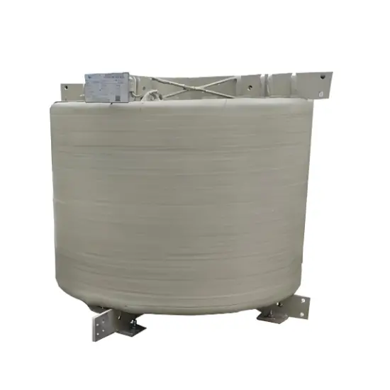
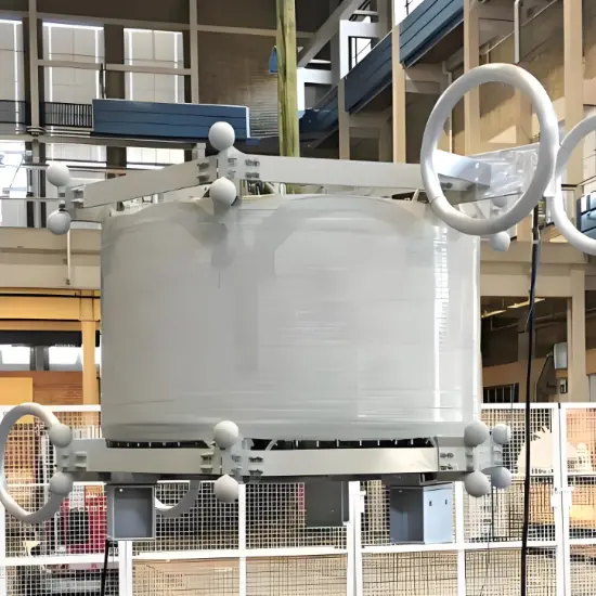
  • The core is made of silicon steel sheet, the core column is divided into uniform small sections through multiple air gaps, the air gap is isolated by epoxy plates, and high-temperature binders are used to ensure that the air gap does not change under the long-term operation of the reactor.

  • The end face of the iron core is made of silicon steel sheet end glue, so that the silicon steel sheet is firmly combined, which greatly reduces the noise during operation and has good corrosion resistance.

  • The coil wrapping structure, the main insulation of the coil is impregnated with glass fiber epoxy resin, and the coil is impregnated with high-temperature insulating paint under vacuum after hot baking and curing, the coil not only has good insulation performance, but also has high mechanical strength, and can withstand the large current impact and cold and hot shock when the motor is started without cracking.

Parameters:

Rated voltage: 6kV, 10kV

Rated frequency: 50Hz, 60Hz

Insulation grade: F

class Starting time: 120S, after 120S, it should be cooled for 6 hours before starting again

企业微信截图_1733189802375.png

企业微信截图_17331897371535.png

Standard:

image.png

Conditions for the use:

  • The altitude does not exceed 2000m.

  • Ambient temperature -25~+45°C, relative humidity ≤90%.

  •  There are no harmful gases around, no flammable and explosive materials.

  •  The waveform of the supply voltage is similar to that of a sine wave.

  • The surrounding environment should be well ventilated, if installed in the cabinet, ventilation equipment should be installed.

  •  Indoors.


What are the differences in the working methods of different types of reactors?

Shunt Reactors:

  • Shunt reactors are primarily used to compensate for capacitive currents, improve power factor, and stabilize grid voltage. They are connected in parallel with the grid and absorb reactive power to regulate the reactive power balance in the grid.

Series Reactors:

  • Series reactors are connected in series within the circuit and are used to limit short-circuit currents, improve the transient stability of the power system, and other purposes. For example, in high-voltage transmission systems, series reactors can limit the short-circuit current during faults, protecting electrical equipment. In power electronic circuits, series reactors can smooth the input current and reduce harmonic distortion.


Know your supplier
Online store
On-time delivery rate
Response time
100.0%
≤4h
Company overview
Workplace: 580000m² Total staff: Highest Annual Export(usD): 120000000
Workplace: 580000m²
Total staff:
Highest Annual Export(usD): 120000000
Services
Business Type: Design/Manufacture/Sales
Main Categories: High Voltage Electrical Apparatus
Whole life care manager
Whole-life care management services for equipment procurement, use, maintenance, and after-sales, ensuring safe operation of electrical equipment, continuous control, and worry-free electricity consumption.
The equipment supplier has passed platform qualification certification and technical evaluation, ensuring compliance, professionalism, and reliability from the source.

Related Products

Related Knowledges

  • Impact of DC Bias in Transformers at Renewable Energy Stations Near UHVDC Grounding Electrodes
    Impact of DC Bias in Transformers at Renewable Energy Stations Near UHVDC Grounding ElectrodesWhen the grounding electrode of an Ultra-High-Voltage Direct Current (UHVDC) transmission system is located close to a renewable energy power station, the return current flowing through the earth can cause a rise in ground potential around the electrode area. This ground potential rise leads to a shift in the neutral-point potential of nearby power transformers, inducing DC bias (or DC offset) in their
    01/15/2026
  • HECI GCB for Generators – Fast SF6 Circuit Breaker
    1.Definition and Function1.1 Role of the Generator Circuit BreakerThe Generator Circuit Breaker (GCB) is a controllable disconnect point located between the generator and the step-up transformer, serving as an interface between the generator and the power grid. Its primary functions include isolating generator-side faults and enabling operational control during generator synchronization and grid connection. The operating principle of a GCB is not significantly different from that of a standard c
    01/06/2026
  • Distribution Equipment Transformer Testing, Inspection, and Maintenance
    1.Transformer Maintenance and Inspection Open the low-voltage (LV) circuit breaker of the transformer under maintenance, remove the control power fuse, and hang a “Do Not Close” warning sign on the switch handle. Open the high-voltage (HV) circuit breaker of the transformer under maintenance, close the grounding switch, fully discharge the transformer, lock the HV switchgear, and hang a “Do Not Close” warning sign on the switch handle. For dry-type transformer maintenance: first clean the porcel
    12/25/2025
  • How to Test Insulation Resistance of Distribution Transformers
    In practical work, insulation resistance of distribution transformers is generally measured twice: the insulation resistance between thehigh-voltage (HV) windingand thelow-voltage (LV) winding plus the transformer tank, and the insulation resistance between theLV windingand theHV winding plus the transformer tank.If both measurements yield acceptable values, it indicates that the insulation among the HV winding, LV winding, and transformer tank is qualified. If either measurement fails, pairwise
    12/25/2025
  • Design Principles for Pole-Mounted Distribution Transformers
    Design Principles for Pole-Mounted Distribution Transformers(1) Location and Layout PrinciplesPole-mounted transformer platforms should be located near the load center or close to critical loads, following the principle of “small capacity, multiple locations” to facilitate equipment replacement and maintenance. For residential power supply, three-phase transformers may be installed nearby based on current demand and future growth projections.(2) Capacity Selection for Three-Phase Pole-Mounted Tr
    12/25/2025
  • Transformer Noise Control Solutions for Different Installations
    1.Noise Mitigation for Ground-Level Independent Transformer RoomsMitigation Strategy:First, conduct a power-off inspection and maintenance of the transformer, including replacing aged insulating oil, checking and tightening all fasteners, and cleaning dust from the unit.Second, reinforce the transformer foundation or install vibration isolation devices—such as rubber pads or spring isolators—selected based on the severity of vibration.Finally, strengthen sound insulation at weak points of the ro
    12/25/2025

Related Solutions

  • Core Value and Innovative Applications of 12kV Medium Voltage Switchgear in Smart Substations​
    With the Rapid Development of Smart Grids and the Integration of Renewable Energy Medium Voltage (MV) Switchgear, as the core power distribution equipment in substations, directly determines the stability of the power system through its reliability, intelligence, and space efficiency. This article delves into the key technologies, scenario-specific solutions, and practical benefits of Medium Voltage Switchgear in substations.Core Requirements for Substation ScenariosHigh Reliability Requirements
    06/12/2025
  • Withdrawable 12kV Medium Voltage Switchgear: The Indispensable Pivot of Flexibility and Safety in Smart Grids
    At the core of medium-voltage power distribution systems in industrial facilities, commercial complexes, and data centers, switchgear acts as a silent commander, governing the lifeline of electrical flow. Among various solutions, ​Withdrawable Switchgear​has become synonymous with reliability in modern MV systems due to its unique design philosophy. Compared to fixed switchgear, its "withdrawable" feature delivers compelling advantages, setting new benchmarks for ​operational efficiency​and ​per
    06/12/2025
  • Core Dilemma in Southeast Asia 12kV Medium Voltage Switchgear​
    Southeast Asia’s rapidly growing power demand (GDP growth >5% annually) combined with extreme climatic conditions—high temperature, humidity, and salt spray corrosion—necessitates balancing lifecycle costs with climate resilience in switchgear selection. This article analyzes the optimal cost-performance solutions between GIS and AIS.​I. GIS vs. AIS Cost Comparison Model (Southeast Asia Context)​​​1. Initial Investment Costs​2. Long-Term Operational Costs​​GIS Advantages:Ext
    06/12/2025
Related Free tools
Haven't found the right supplier yet? Let matching verified suppliers find you. Get Quotation Now
Haven't found the right supplier yet? Let matching verified suppliers find you.
Get Quotation Now
Send inquiry
+86
Click to upload file

IEE Business will not sell or share your personal information.

Download
Get the IEE Business Application
Use the IEE-Business app to find equipment, obtain solutions, connect with experts, and participate in industry collaboration anytime, anywhere—fully supporting the development of your power projects and business.