• 550kV HV Gas Insulated Switchgear (GIS)
550kV HV Gas Insulated Switchgear (GIS)
discuss personally
Model
ZF27-550/6300-63
Basic info
Brand ROCKWILL
Model NO. 550KV GIS Gas Insulated Switchgear (GIS)
Rated voltage 550kV
Rated normal current 6300A
Series ZF27
Product Detail

Description:


The ZF27 - 550, an independently developed 550KV - level Gas Insulated Switchgear (GIS), boasts technical parameters at the international leading edge. Tailored for 550KV power systems, it enables seamless control, measurement, and protection. Comprising key components like circuit breakers, disconnectors, earthing switches, quick earthing switches, current transformers, busbars, and air - insulated bushings for power inlets and outlets, other components are enclosed in an earthed shell with SF6 gas serving as both arc - extinguishing and insulating medium. It can be flexibly configured into various connection modes per user needs.


Main Features:


  • The circuit breaker features a single - fracture arcing chamber with a simple, rational structure and advanced technology.

  • It offers robust breaking capabilities, an extended electrical contact lifespan, and a long service life.

  • The circuit breaker unit can be installed on - site without opening the chamber and filled with SF6 gas directly, preventing dust and foreign matter ingress.

  • The innovative hydraulic operating mechanism has minimal external piping, reducing the likelihood of oil leakage.

  • During operation, the hydraulic operating mechanism is automatically regulated by the pressure switch, maintaining a constant rated oil pressure regardless of ambient temperature. Its relief valve safeguards against overpressure risks.

  • In case of pressure loss, the hydraulic operating mechanism prevents slow tripping during pressure restoration.

  • The closing resistance of the product can be optionally installed or removed based on user requirements.

Technical Parameters:

1718679970148.png

What are the technical parameters of gas-insulated Switchgear?

Rated Voltage:

  • Common rated voltage levels include 72.5kV, 126kV, 252kV, 363kV, and 550kV. The rated voltage determines the maximum operating voltage that the equipment can withstand and is a crucial factor in the design and selection of GIS (Gas-Insulated Switchgear) equipment. It must match the voltage level of the power system to ensure that the equipment operates safely and reliably under both normal and fault conditions.

Rated Current:

  • The rated current ranges from a few hundred amperes to several thousand amperes, such as 1250A, 2000A, 3150A, 4000A, etc. The rated current indicates the maximum current that the equipment can carry continuously without damage. When selecting the equipment, it is necessary to consider a certain margin based on the actual load conditions to ensure that the equipment does not fail due to overload during normal operation and can also meet future load growth requirements.

Rated Short-Circuit Breaking Capacity:

  • Typically, the rated short-circuit breaking capacity ranges from 31.5kA to 63kA or even higher. This parameter measures the equipment's ability to interrupt short-circuit currents. When a short-circuit fault occurs in the power system, the short-circuit current increases dramatically. The GIS equipment must be able to quickly and reliably interrupt the short-circuit current to prevent the fault from escalating. The rated short-circuit breaking capacity must be greater than the maximum possible short-circuit current in the system to ensure the safety performance of the equipment during a short-circuit condition.

SF₆ Gas Pressure:

  • The rated pressure of SF₆ gas in the equipment is generally between 0.3MPa and 0.7MPa. The actual operating pressure may be adjusted according to the specific requirements of the equipment and environmental factors such as temperature. During operation, it is necessary to monitor and control parameters such as the pressure, humidity, and purity of the SF₆ gas to ensure they remain within specified limits. This ensures the insulation and arc-quenching performance of the equipment.


Know your supplier
ROCKWILL
Rockwill Electric Group Global Manufacturer of High voltage and medium-voltage power equipment and smart grid solutions. Headquartered in Wenzhou, China. Serving 100+ countries with quality, innovation, and trust. What We Offer: • HV-MV switchgear (VCB, SF₆ circuit breakers, RMU, GIS) • Distribution transformers and substations • Smart grid and monitoring systems • Solar, wind, EV charging, and energy storage solutions • EPC turnkey power projects Certified: ISO 9001 / ISO 14001 / ISO 45001
Main Categories
High Voltage Electrical Apparatus
Business Type
Design/Manufacture/Sales
Highest Annual Export (USD)
$150,000,000
Professional Experience
16 years
Workplace
108000m²m²
占位
占位
Related Products
Related Knowledges
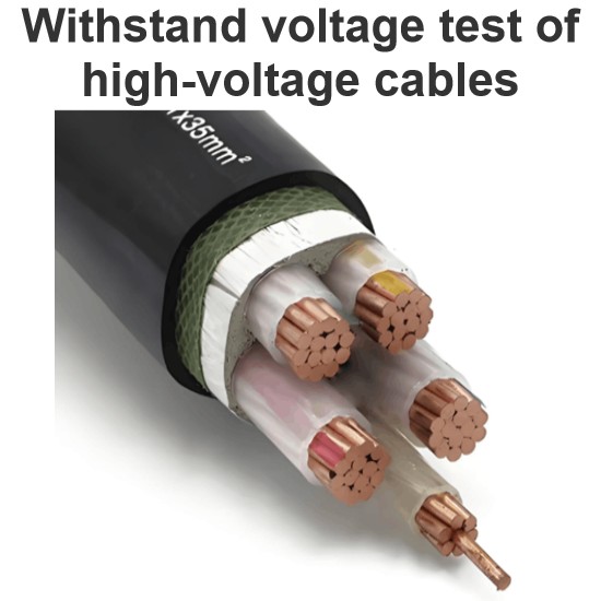
Withstand voltage test of high-voltage cables
Withstand voltage test is an insulation test, but it is a destructive test that can reveal insulation defects difficult to detect in non-destructive testing.The test cycle for high-voltage cables is three years, and it must be conducted after non-destructive tests. In other words, the withstand voltage test is performed only after all non-destructive tests have been passed.Most high-voltage cables used today are cross-linked polyethylene (XLPE) cables, which can have large cross-sections and cov
Oliver Watts
09/03/2025
Analysis of Abnormal Causes of High-Voltage Cable Grounding Circulation and Typical Cases
I. Introduction to Cable Grounding Loop CurrentCables rated 110 kV and above use a single-core structure. The alternating magnetic field generated by the operating current induces a voltage on the metallic sheath. If the sheath forms a closed circuit through the earth, a grounding loop current will flow on the metallic sheath. Excessive grounding loop current (loop current exceeding 50 A, more than 20% of the load current, or a ratio of maximum-to-minimum phase current greater than 3) not only a
Felix Spark
09/03/2025
Considerations and Recommendations for Flame-Retardant Selection of High-Voltage Cables
1.Flame-Retardant Cable Classification StandardsThe flame-retardant standard system is divided into two main categories. The first category follows the "Classification of Burning Behavior for Electric and Optical Fiber Cables" GB 31247. Cables complying with this standard system are widely used in densely populated areas such as high-speed railways and subways. This standard imposes strict requirements on parameters such as smoke density, heat release, and total smoke production, and cables typi
James
09/03/2025
Repair of high-voltage cable metallic sheaths
I. Functions of Metallic Sheaths and Necessity of RepairThe metallic sheath of high-voltage cables is a metal shielding structure laid outside the insulation layer, including types such as lead sheaths, aluminum sheaths, and steel wire armor. Its core functions include mechanical protection (resisting external impact and compression), electrochemical corrosion protection (isolating moisture and soil pollutants), electromagnetic shielding (reducing electromagnetic interference to the environment)
Felix Spark
09/03/2025
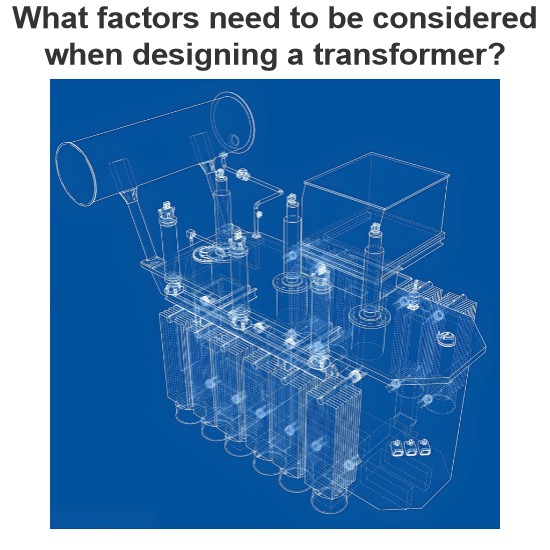
What factors need to be considered when designing a transformer?
Transformer design is a complex process that requires consideration of multiple factors to ensure safe and efficient operation. In addition, compliance with international and local regulations is essential to guarantee that transformers meet safety and performance standards. Below are key factors to consider in transformer design and the relevant regulations to follow:Transformer Design Factors: Voltage and Frequency: Determine the input and output voltage levels and the operating frequency. The
Vziman
09/02/2025
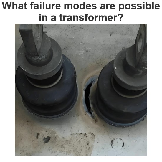
What failure modes are possible in a transformer? How to identify and fix these failures?
Transformers are critical components in power systems, and various failure modes can affect their operation. Timely identification and resolution of these failure modes are essential to prevent costly downtime and ensure system reliability. Below are some common transformer failure modes, along with methods to identify and address them: Insulation FailureIdentification: Insulation failure leads to decreased insulation resistance, which can be detected through insulation resistance testing (megge
Edwiin
09/02/2025
×
Inquiry
Download
IEE-Business is dedicated to serving the personnel in the global power industry.
Join IEE-Business, not only can you discover power equipment and power knowledge, but also canhnd like - minded friends!