Analysis of Grounding Transformer Operational Behavior Under System Single-Phase-to-Ground Fault Conditions

1 Theoretical Analysis
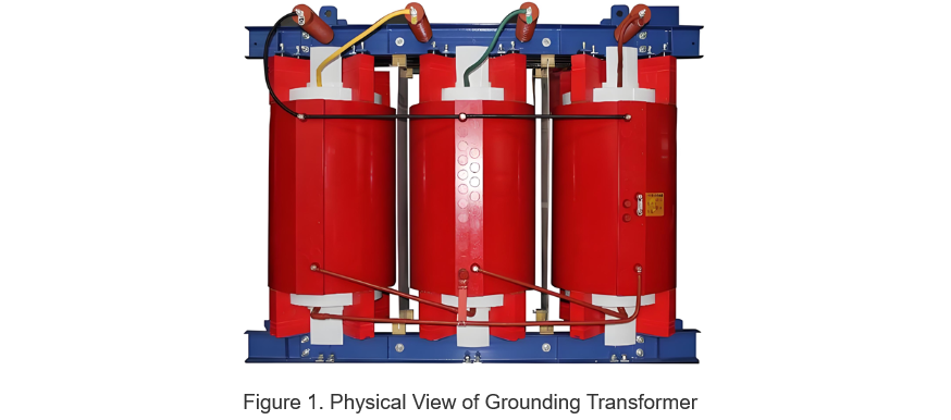
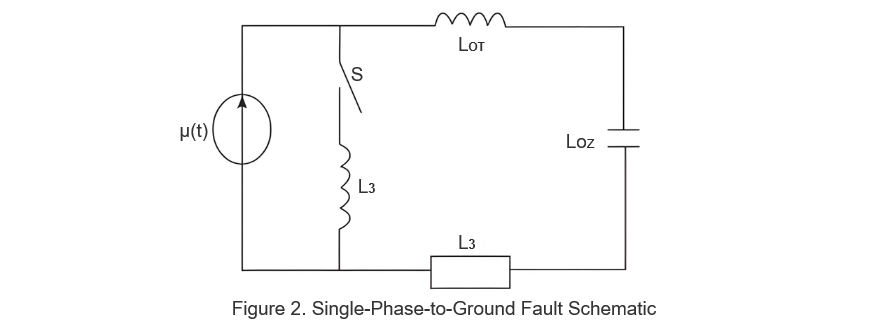
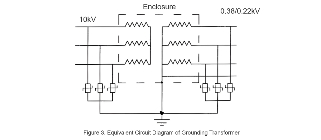
In distribution networks, grounding transformers serve two key roles: powering low - voltage loads and connecting arc - suppression coils at neutrals for grounding protection. Grounding faults, the most common distribution network fault, heavily impact transformers’ operating characteristics, causing sharp changes in electromagnetic parameters and status.To study transformers’ dynamic behaviors under single - phase grounding faults, build this model: Assume a transformer’s inherent characteristics stay stable during low - voltage side single - phase faults. Then, deduce its operating rules via the arc - suppression coil’s compensation mechanism. Relevant materials include: Figure 1 (transformer physical structure), Figure 2 (system equivalent circuit under single - phase fault), and Figure 3 (transformer operational equivalent circuit).
u represents the voltage of the virtual power source, and its calculation formula is:

n the formula:Um is the voltage amplitude of the bus; w0 is the power - frequency angular frequency; w0 is the voltage phase angle generated after the system experiences a single - phase grounding fault. During a fault in the arc - burning stage, the current iL of the arc - suppression coil is:

In the formula: δ1 is the attenuation factor; IL represents the amplitude of the system current and inductance; R1 is the equivalent resistance of the main transformer and the line - mode loop; e is the voltage phase angle when a single - phase grounding fault occurs; L denotes the zero - sequence inductance of the grounding transformer and the inductance of the arc - suppression coil.
There is a correlation between the inductive current and the detuning degree in the arc-suppression coil, and the following formula can be derived:

In the formula:iC is the compensated grounding current; C is the capacitance - to - ground of the distribution line; v is the detuning degree of the substation system. When the single - phase grounding fault of the system is in a stable grounding state, the inductive current of the arc - suppression coil tends to be stable.
Combining the above analysis, the following equation can be derived:

In the formula:RL is the equivalent resistance of the main transformer and the line - mode loop (the original “equivalent inductance” is likely a typo; corrected to “equivalent resistance” based on circuit logic; if it is indeed inductance, retain the symbol LL); w0 is the power - frequency angular frequency.
The formula (4) can be substituted into formula (5) to calculate the inductive current, and the following formula is obtained:

Combined with Formula (6), during the arc - extinction stage of the fault, the inductance of the arc - suppression coil and the capacitance - to - ground of the distribution line are connected in series, and the system current is uniform. After the inductive current returns to normal, the calculation formula for the inductive current is as follows:

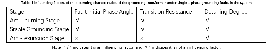
In the formula: uC0+is the capacitance - to - ground voltage of the system during the arc - extinction stage; iL0+ is the inductive current flowing through the arc - suppression coil of the system during the arc - extinction stage; w is the resonant angular frequency. Based on the above analysis, in different stages of the single - phase grounding fault of the system, the influencing factors on the operating characteristics of the grounding transformer are different, as specifically shown in Table 1.
2 Construction and Verification of the Simulation Model
2.1 Model Construction
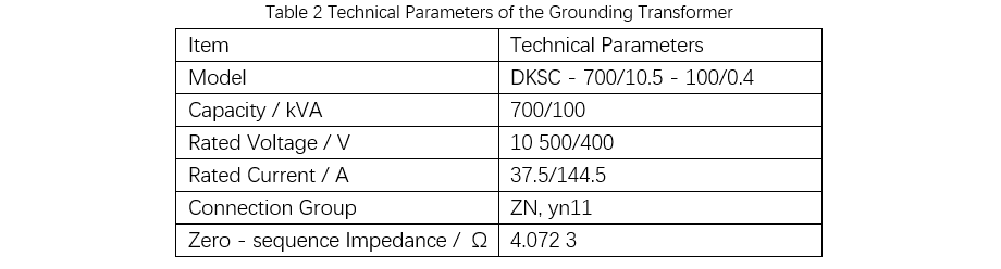
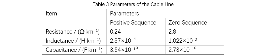
The establishment of the simulation model is based on the parameters of the grounding transformer in a certain region, as detailed in Table 2. The parameters of the cable line are shown in Table 3.
2.2 Model Verification
In model verification, to ensure the authenticity and validity of the research, a single - phase grounding fault of the system can be set at a location 4 km away from the 1 A cable line and the 10 kV bus. The fault phase angle takes 90° as the reference. Use the constructed simulation model to obtain the zero - sequence currents of different lines in the system's single - phase grounding fault, as detailed in Table 4.
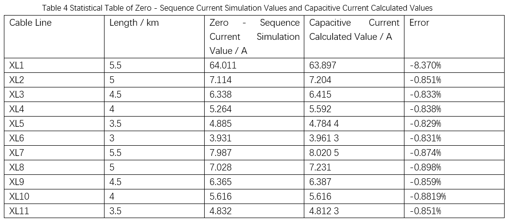
When a single - phase grounding fault occurs in the system, the calculation formula for the capacitive current of different lines of the grounding transformer is:

Combined with the data in Table 4, when a single - phase grounding fault occurs in the system, the maximum error between the simulation value of the zero - sequence current of the non - faulty line and the calculated value of the actual capacitance - to - ground current is -0.848%, and there is no significant difference.
3 Simulation Analysis of Operating Characteristics
3.1 Influence of Fault Initial Phase Angle
In the arc - burning stage, three - phase voltages deform significantly. Phase A, B, and C voltages rise, expanding the initial fault phase angle and increasing voltage distortion. In the stable stage, a larger initial phase angle shortens the three - phase voltage stabilization time. In the arc - extinction stage, despite different initial phase angles, phase voltages change consistently: Phase A rises to normal amplitude; Phase B drops to normal; Phase C first drops below normal then rises back. For currents: In the first arc - burning stage, a larger initial phase angle reduces three - phase current variation; in the stable stage, it increases variation; in the arc - extinction stage, current changes are uniform regardless of initial phase angles.
3.2 Influence of Transition Resistance
In the arc - burning stage of a single - phase grounding fault, a smaller transition resistance of the grounding transformer increases three - phase voltage variation; in the stable stage, it amplifies voltage variation (Phase B and C amplitudes are smaller). In the arc - extinction stage, three - phase voltages are consistent under different resistances: Phase A reaches normal amplitude, Phase B drops to normal, and Phase C drops then rises. For currents: In the arc - burning stage, a smaller resistance boosts three - phase current amplitude. The first stage (large resistance) has small current amplitude; the second (small resistance) has large amplitude; in the third stage, with the arc - suppression coil stopped, Phase A and C currents first drop then rise to normal.
4 Conclusion
A single - phase grounding fault in the substation system increases three - phase currents on the grounding transformer side (consistent phases, no harm to equipment). To ensure stable, safe power supply, understand the transformer’s operation and factor impacts after faults. As substation operation is affected by multiple factors, power enterprises should prioritize system inspections, improve inspection work, ensure distribution line operation, resolve single - phase grounding faults, and support daily life.


