
With the expansion of power system scale and the cableization process of urban power grids, the capacitive current in 6kV/10kV/35kV power grids has significantly increased (generally exceeding 10A). As power grids at this voltage level mostly adopt neutral ungrounded operation mode, and the distribution voltage side of main transformers is usually in delta connection, lacking a natural grounding point, the arc during ground faults cannot be reliably extinguished, necessitating the introduction of grounding transformers. Z-type grounding transformers have become the mainstream due to their small zero-sequence impedance, but some systems require lower zero-sequence impedance. The smaller the impedance value, the greater the deviation, which requires targeted measures in the design of low zero-sequence impedance grounding transformers.
1. Calculation Method of Zero-sequence Impedance for Z-type Grounding Transformer
1.1 Topological Structure
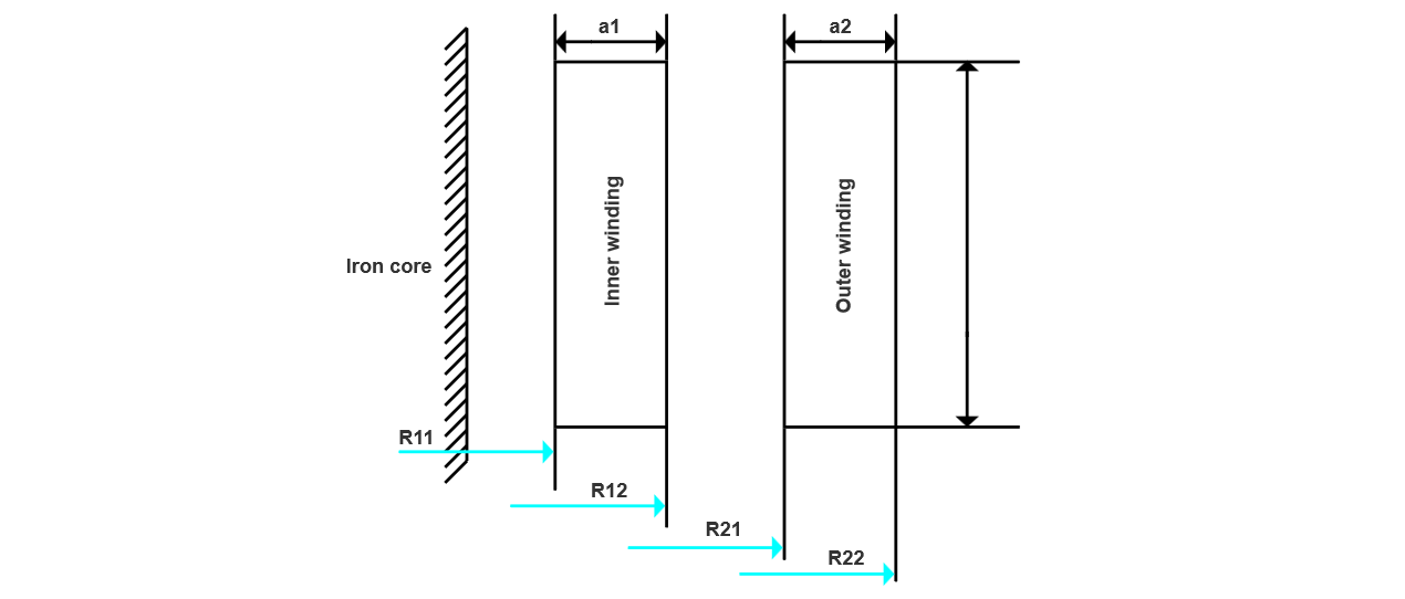
The high-voltage winding of Z-type grounding transformer adopts a zigzag connection. Each phase winding is divided into upper and lower half-windings (as shown in Figure 1), which are respectively wound on different iron core columns. The two half-windings of the same phase are connected in series with reverse polarity, forming a special magnetoelectric coupling structure.
The zero-sequence impedance is calculated as shown in equation (1).

In the formula, X0 is the zero - sequence impedance, W is the number of turns of one winding (that is, a half - winding), ΣaR is the equivalent leakage magnetic area, ρ is the Lorenz coefficient, and H is the reactance height of the winding.
2 Analysis of Zero - sequence Impedance Deviation
According to the IEC 60076 - 1 standard, the zero - sequence impedance deviation of a grounding transformer is judged to be qualified if it is within the range of ±10%. Through the analysis of the test results of hundreds of grounding transformers (including oil - immersed and dry - type) produced by the company in recent years, and by comparing the differences between the actual measured values and the design values of the zero - sequence impedance, the differences can be roughly divided into the following three categories:
Due to the different requirements for zero - sequence impedance by different users, there are various types of grounding transformers. Among them, the 35kV class has the highest proportion, followed by the 10kV class. Generally, for 35kV class grounding transformers, the zero - sequence impedance is mostly required to be ≤ 120Ω; for the 10kV class, it is usually required to be ≤ 15Ω. Some users have smaller requirements, and some do not make clear requirements.
3 Data Analysis
Comprehensively considering the test results of multiple grounding transformers, the root cause of the large deviation of the zero - sequence impedance lies in that the value required by the user deviates too much from the conventional impedance value. Both too large and too small values will bring great challenges to production and manufacturing. It can be seen from Formula (1) that the zero - sequence impedance has a square relationship with the number of turns, which is the most critical factor affecting the zero - sequence impedance: the more the number of turns, the greater the amount of wire used; the fewer the number of turns, the corresponding increase in the amount of iron core used. Whether the zero - sequence impedance is too large or too small, it will significantly increase the production cost.
3.1 Case Analysis
Take two batches of small - capacity 10kV grounding transformers as examples for analysis:
By comparison, the deviation of the oil - immersed type is slightly larger than that of the dry - type. The reason is that when designing for a very small zero - sequence impedance, the number of turns is small, the radial size of the winding is small, and the height is relatively high, so the zero - sequence value is difficult to control. When the base value is small, poor control of the size easily leads to the amplification of the deviation; while the dry - type winding is cast with resin, and the external dimension is easier to control with the help of a mold, so the deviation is relatively smaller.
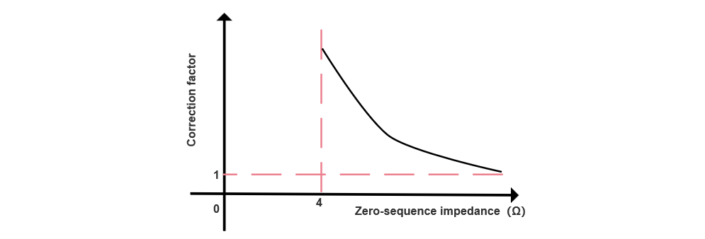
The actual production data shows that the existing calculation method is not applicable to the grounding transformer with low zero - sequence impedance. Combined with the statistical data of previous products, it is speculated that a correction coefficient should be introduced, and different zero - sequence values correspond to different correction coefficients: as the zero - sequence value increases, the coefficient decreases non - linearly; when the zero - sequence value reaches about 10Ω, the coefficient approaches 1.0; after exceeding 10Ω, affected by the slight differences in the production process, the coefficient changes little (there are occasional cases where it is less than 1.0, and the overall deviation is low), and the form of expression is approximately an inverse proportion function in the first quadrant (see Figure 2).
It should be noted that the above analysis is only applicable to 10kV products. For products above 10kV, since there is no such strict requirement for low zero-sequence impedance, the phenomenon of excessive zero-sequence impedance deviation has not been found so far.
4 Solutions
To address the issue of excessive measured zero-sequence impedance in low zero-sequence impedance grounding transformers, the following optimization measures are proposed based on data collection and analysis:
4.1 Design Optimization Strategy
When users require an extremely small zero-sequence impedance value, the precision of winding dimensions is difficult to ensure, easily amplifying measurement deviations. For products with a required zero-sequence impedance <5Ω, a design margin of 2-5 times should be reserved. The smaller the impedance value, the larger the margin needed to ensure measured values meet requirements.
4.2 Manufacturing Control Points
The production process plays a decisive role in ensuring product performance accuracy:
4.3 Technical Agreement Recommendations
5 Conclusion
For low zero-sequence impedance grounding transformers, significant deviations exist between design values calculated by general formulas and actual measurements. It is recommended to evaluate manufacturability at the ordering stage, introduce correction factors during design, and reserve sufficient production margins to enhance product consistency and delivery reliability.


