• Product
  • Suppliers
  • Manufacturers
  • Solutions
  • Free tools
  • Knowledges
  • Experts
  • Communities
Search


Dielectric Withstand Capability of AC Vacuum Contactors and Countermeasures

Felix Spark
Felix Spark
Field: Failure and maintenance
China

During operation, AC vacuum contactors are often subjected to various overvoltages such as lightning overvoltage and switching overvoltage. Therefore, AC vacuum contactors must have a certain voltage withstand capacity.

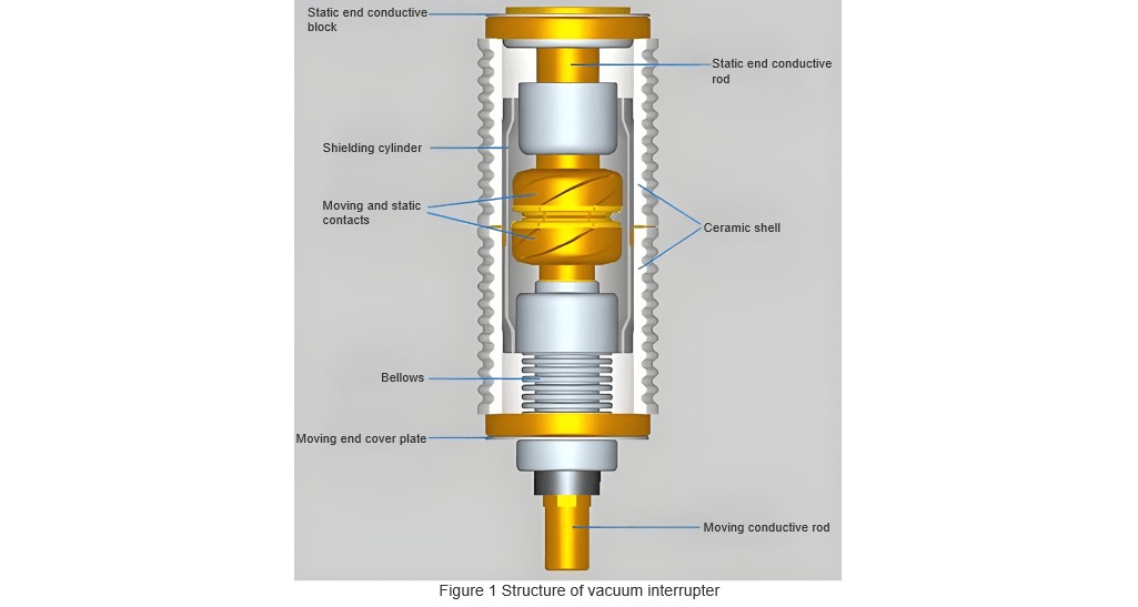
An AC vacuum contactor is composed of a vacuum interrupter (its structure is shown in Figure 1), a housing, an electromagnetic system, a secondary circuit, and other components. Among these, the vacuum interrupter is the "heart" of the AC vacuum contactor, and its performance directly affects the voltage withstand capacity of the AC vacuum contactor.

Figure 1 Structure of vacuum interrupter.jpg

1. Influencing Factors and Hazards

After the design and manufacture of a vacuum interrupter are completed, the gap d between its moving and static contacts remains unchanged. Therefore, the magnitude of the gap breakdown voltage mainly depends on the pressure p, that is, the vacuum degree of the vacuum interrupter. When the vacuum degree is relatively high, the relative density of electrons is very low, and of course, the number of charged particles is also small. The discharge capacity of the gas is very weak, so the breakdown voltage is large, and the voltage withstand capacity of the vacuum interrupter is strong. Therefore, theoretically, the higher the vacuum degree, the lower the pressure, the higher the dielectric strength of the contact gap, the higher the breakdown voltage, the stronger the voltage withstand capacity of the vacuum interrupter, and at this time, the leakage current is smaller.

The factors affecting the voltage withstand capacity of the vacuum interrupter, in addition to the charged particles existing in the contact gap (the vacuum degree plays a major role), are also related to the outer shell of the vacuum interrupter. As shown in Figure 1, the outer shell of the vacuum interrupter is made of ceramic or glass. Since ceramic and glass are both hydrophilic insulating materials, they have a strong ability to absorb water, and water absorbs impurities. Under the action of an applied voltage, these impurities are easily ionized into charged particles and cause surface discharge, reducing the voltage withstand capacity of the vacuum interrupter. At this time, the insulation strength of the shell decreases, and the leakage current increases.

Under the action of an applied voltage, the main contact gap of the vacuum interrupter and the outer shell of the vacuum interrupter form a parallel circuit. If the surface discharge of the vacuum interrupter develops into a flashover, it indicates that the vacuum interrupter breaks down along the surface of the shell, seriously affecting the insulation performance of the vacuum interrupter. In addition, for the AC vacuum contactor, the quality of the outer shell is also a factor affecting its voltage withstand capacity.

2. Improvement Measures

Since the voltage withstand capacity of the AC vacuum contactor mainly depends on the vacuum interrupter, and the factors affecting the voltage withstand capacity of the vacuum interrupter include the inside of the interrupter and the outer shell, measures should be taken from these two aspects for improvement.

First, from the perspective of the inside of the vacuum interrupter, attention should be paid to the following aspects:

Improve the physical structure of the contacts to make the electric field of the vacuum interrupter as uniform as possible. When the contact gap of the vacuum interrupter is determined, improving the distribution of the electric field in the interrupter to make it more uniform helps to improve the voltage withstand capacity of the vacuum interrupter and reduce the leakage current.

In practice, first, the thickness of the contacts should be appropriately increased, and the sharp corners and edges of the contacts should be blunted, so that the electric field distribution at these parts is not too concentrated, thereby helping to improve the voltage withstand capacity of the vacuum interrupter. In addition, for high-voltage and large-capacity vacuum interrupters, a voltage-equalizing shield should also be designed around the contacts, and an auxiliary voltage-equalizing shield should be designed at the end of the voltage-equalizing shield to effectively improve the electric field distribution near the contacts. Designing end shields near the end caps at both ends of the vacuum interrupter can effectively reduce the electric field intensity near the end caps of the vacuum interrupter.

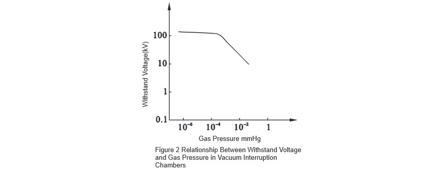
Improve the vacuum degree. The vacuum degree is an important parameter reflecting the quality of the vacuum interrupter. The vacuum degree of a qualified vacuum interrupter has a range, between 10^-4~ 10^-2 Pa, that is, 10^-6~10^-4 mmHg As shown in Figure 2, when the pressure of the vacuum interrupter is greater than 10^-2 Pa, its voltage withstand capacity decreases rapidly.

Relationship Between Withstand Voltage and Gas Pressure in Vacuum Interruption Chambers.jpg

The contact surface should be smooth and flat. If necessary, burrs on the contact surface should be removed through conditioning.

Improve the coaxiality. The guide sleeve can effectively ensure the coaxiality of the vacuum interrupter, but sometimes the coaxiality is still not in the best state and needs to be carefully adjusted. The improvement of coaxiality ensures the effective contact of the moving and static contacts, which can reduce the contact resistance, reduce the heat generated when the contacts are closed, and effectively reduce the surface damage caused by fusion welding when the contacts are opened.

Second, from the perspective of the outer shell of the vacuum interrupter, attention should be paid to the following aspects:

  • Increase the creepage distance. Especially in the case of product miniaturization, this goal can be effectively achieved by designing the outer shell into a corrugated shape.

  • Maintain the cleanliness of the outer shell and pay attention to the use environment. Especially for vacuum switches used outdoors in polluted and humid environments, measures should be taken to keep the outer shell clean.

  • For high-voltage and large-capacity vacuum interrupters, adding silicone grease insulation between the outer surface of the vacuum interrupter and the insulating porcelain sleeve can effectively improve the insulation strength of the outer surface of the vacuum interrupter. In addition, materials with high insulation strength must be selected to improve the voltage withstand capacity of the outer shell of the AC vacuum contactor.

3. Conclusion

By improving the internal insulation of the vacuum interrupter and reducing the surface conductivity of the outer shell of the vacuum interrupter, and improving the voltage withstand capacity of the outer shell of the AC vacuum contactor, the voltage withstand capacity of the AC vacuum contactor can be greatly improved, and the product quality can be enhanced.

Give a tip and encourage the author!
Recommended
10kV RMU Common Faults & Solutions Guide
Application Issues and Handling Measures for 10kV Ring Main Units (RMUs)The 10kV ring main unit (RMU) is a common electrical distribution device in urban power distribution networks, primarily used for medium-voltage power supply and distribution. During actual operation, various issues may arise. Below are common problems and corresponding corrective measures.I. Electrical Faults Internal Short Circuit or Poor WiringA short circuit or loose connection inside the RMU can lead to abnormal operati
Echo
10/20/2025
High-Voltage Circuit Breaker Types & Fault Guide
High-Voltage Circuit Breakers: Classification and Fault DiagnosisHigh-voltage circuit breakers are critical protective devices in power systems. They rapidly interrupt current when a fault occurs, preventing damage to equipment from overloads or short circuits. However, due to long-term operation and other factors, circuit breakers may develop faults that require timely diagnosis and troubleshooting.I. Classification of High-Voltage Circuit Breakers1. By Installation Location: Indoor-type: Insta
Felix Spark
10/20/2025
10 Prohibitions for Transformer Installation and Operation!
10 Prohibitions for Transformer Installation and Operation! Never install the transformer too far away—avoid placing it in remote mountains or wilderness. Excessive distance not only wastes cables and increases line losses, but also makes management and maintenance difficult. Never choose transformer capacity arbitrarily. Selecting the right capacity is essential. If the capacity is too small, the transformer may be overloaded and easily damaged—overloading beyond 30% should not exceed two hours
James
10/20/2025
How to Maintain Dry-Type Transformers Safely?
Maintenance Procedures for Dry-Type Transformers Put the standby transformer into operation, open the low-voltage side circuit breaker of the transformer to be maintained, remove the control power fuse, and hang a "DO NOT CLOSE" sign on the switch handle. Open the high-voltage side circuit breaker of the transformer under maintenance, close the grounding switch, fully discharge the transformer, lock the high-voltage cabinet, and hang a "DO NOT CLOSE" sign on the switch handle. For dry-type trans
Felix Spark
10/20/2025
Send inquiry
Download
Get the IEE Business Application
Use the IEE-Business app to find equipment, obtain solutions, connect with experts, and participate in industry collaboration anytime, anywhere—fully supporting the development of your power projects and business.