A Guide to the Latest Transformer Testing Technologies

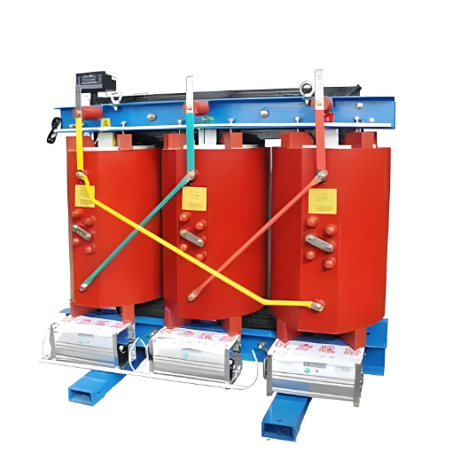
Transformers come in many types, primarily oil-immersed and dry-type. Their fault manifestations are diverse, but most failures are concentrated in the windings, core, connecting components, and oil contamination. For example, winding insulation damage, open circuits, short circuits, and inter-turn short circuits at connection points. Common external symptoms of transformer faults include severe overheating, excessive temperature rise, abnormal noise, and three-phase imbalance.
Routine transformer maintenance mainly includes insulation testing (insulation resistance, dielectric absorption ratio, etc.), DC resistance measurement (for detecting winding-related faults), core lifting inspection, and no-load tests. Some enterprises also analyze the oil quality of oil-immersed transformers to ensure that its electrical insulation and thermal performance remain intact.
Below are several advanced transformer testing methods for reference.
1. ALL-Test Method
The core of the ALL-Test method is to use high-frequency, low-voltage signals—instead of high-voltage signals—to measure internal parameters such as DC resistance, impedance, winding inductance phase angle, and the current-to-frequency ratio (I/F) of winding-based equipment. This allows for accurate assessment of internal faults and their development stages. The advantages of this method are:
Enables rapid on-site fault diagnosis, helping determine whether further time-consuming and labor-intensive inspections—such as core lifting—are necessary.
High measurement accuracy. Since transformer winding DC resistance is typically very low, using low-voltage high-frequency signals avoids aggravating existing defects. With precision up to three decimal places, even minor inter-turn short circuits can be detected through noticeable changes in DC resistance (R)—something conventional DC resistance testing cannot achieve.
Facilitates condition-based monitoring. Each measurement can be recorded and stored. By conducting regular tests and plotting trend curves, changes in key parameters can be monitored over time, providing reliable data for early fault detection and predictive maintenance—supporting quantitative fault management in industrial facilities.
Comprehensive parameter analysis (R, Z, L, tgφ, I/F) offers a more complete, timely, and accurate description of internal transformer faults.
Basic Procedure for ALL-Test:
After disconnecting power to the transformer, ground the secondary (or primary) side. Then connect the instrument’s signal leads to the primary (or secondary) terminals (H1, H2, H3) one by one, measuring inter-phase parameters (R, Z, L, tgφ, I/F). By comparing results between phases or against historical data from the same phase at different times, the fault condition of the transformer can be determined.
As a reference, the following are recommended empirical evaluation criteria:
Resistance (R):
If R > 0.25 Ω, a phase-to-phase difference exceeding 5% indicates three-phase imbalance.
If R ≤ 0.2 Ω, use a 7.5% threshold for imbalance judgment.
Impedance (Z):
Inter-phase imbalance should not exceed 5%.
Failed transformers often show imbalance trending toward over 100%.
Inductance (L):
Imbalance must not exceed 5%.
Phase Angle Tangent (tgφ):
Difference between phases should be within one digit (e.g., 0.1 vs 0.2 is acceptable; 0.1 vs 0.3 is not).
Current-to-Frequency Ratio (I/F):
Inter-phase difference should not exceed two digits (e.g., 1.23 vs 1.25 is acceptable).
Based on field experience, during the progression from imbalance to failure, transformer test data undergoes dramatic changes. For critical transformers, it is recommended to perform ALL-Test measurements at least once per month.
Table 1 Experimental data of a good 2500kVA, 28800:4300 transformer, secondary side test
| H₁ - H₂ | H₁ - H₃ | H₂ - H₃ | |
| R | 0.103 | 0.100 | 0.096 |
| Z | 15 | 14 | 14 |
| L | 2 |
2 | 2 |
| tgφ | 75 | 75 | 75 |
| I/F | -48 | -48 | -49 |
Table 2 Experimental data of a faulty 500kVA, 13800:240V transformer, primary side test
| H₁ - H₂ | H₁ - H₃ | H₂ - H₃ | |
| R | 116.1 | 88.20 | 48.50 |
| Z | 4972 | 1427 | 1406 |
| L | 7911 | 2267 | 2237 |
| tgφ | 23 |
21 | 20 |
| I/F | -33 | -29 |
-29 |
2. Turns Ratio Test Method
In field testing of transformers, directly measuring the turns ratio is an effective and quick method for detecting internal faults—such as incorrect wiring, short circuits, or open circuits. During operation, due to manufacturing variations or insulation degradation over time, the actual turns ratio of a transformer may deviate from its nameplate value. If measured accurately, the turns ratio can serve as a key condition indicator to identify and track the development of internal defects. To address this, a transformer turns ratio (TTR) tester is used, which typically requires very high measurement precision.
3. Transformer Oil Quality Testing
Oil-immersed transformers are widely used, and a critical part of their maintenance is assessing the condition of the insulating oil. Signs of oil degradation—such as darkened color, acidic odor, reduced dielectric strength (breakdown voltage), or sludge formation—can often be identified through visual inspection. In addition, quantitative analysis of key oil properties—including viscosity, flash point, and moisture content—is essential for a comprehensive assessment. Refer to the table below for evaluation criteria.
| Serial Number | Item | Equipment Voltage Class (kV) | Quality Index | Inspection Method | |
| Oil Before Putting into Operation | Oil in Operation | ||||
| 1 |
Water - soluble Acid (pH Value) | >5.4 | ≥4.2 | GB7598 | |
| 2 | Acid Value (mgKOH/G) | ≤0.03 | ≤0.1 | GB7599 or GB264 | |
| 3 | Flash Point (Closed Cup) | >140 (for No. 10, 25 Oil) >135 (for No. 45 Oil) |
1. Not lower than the new oil standard by 5 2. Not lower than the previous measured value by 5 |
GB261 | |
| 4 | Mechanical Impurities | None | None | Visual Inspection | |
| 5 | Free Carbon | None | None | Visual Inspection | |
The following briefly introduces how to perform analysis and inspection using gas chromatography. When transformer oil deteriorates or faults occur, the basic approach of this method is to extract an oil sample from the transformer without shutting down power, analyze the types and concentrations of dissolved gases, and then determine the fault condition. Under normal conditions, the gas content in oil is very low, especially combustible gases, which account for only 0.001% to 0.1% of the total.
However, as the severity of transformer faults increases, the oil and solid insulation materials generate various gases under thermal and electromagnetic effects due to thermal faults. For example, when there is localized overheating, insulating materials produce large amounts of CO and CO₂; when the oil itself overheats, it generates significant quantities of ethylene and methane. Using combustible gas content as a judgment criterion, the following guidelines can be applied: gas content below 0.1% indicates normal condition; 0.1% to 0.5% indicates mild fault; above 0.5% indicates severe fault.
Gases mainly produced by electrical faults in transformers are hydrogen and acetylene (C₂H₂), primarily caused by arc discharge or sparking. The following reference indicators can be used for judgment: H₂ content <0.01% is normal, 0.01–0.02% requires attention, and >0.02% indicates a fault; C₂H₂ <0.0005% is normal, and >0.001% indicates a fault.
After a transformer becomes damp, the H₂ (hydrogen) content tends to be high, because hydrogen gas is generated through electrolysis under current. These gas data can be comprehensively analyzed to assess the transformer’s condition.