Vacuum Circuit Breaker Withstand Voltage Test Guide

Insulation Withstand Voltage Test Standards for Vacuum Circuit Breakers
The main purpose of the insulation withstand voltage test for vacuum circuit breakers is to verify whether the insulation performance of the equipment under high voltage is qualified, and to prevent breakdown or flashover accidents during operation. The test process must be strictly carried out in accordance with power industry standards to ensure equipment safety and power supply reliability.
Test Objects
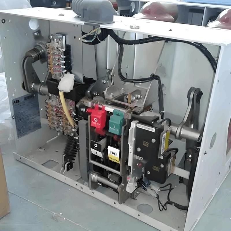
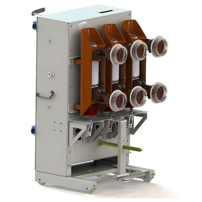
The test objects include the main circuit, control circuit, secondary circuit, insulating support components, and the enclosure body of the circuit breaker.
The main circuit includes live parts such as moving contacts, fixed contacts, and conductive rods.
The control circuit includes low-voltage components such as trip and close coils, auxiliary switches, etc.
Test Voltage Standards
Power frequency withstand voltage test reference values:
Main circuit of 10kV circuit breaker — 42kV / 1 minute
Main circuit of 35kV circuit breaker — 95kV / 1 minute
Between secondary circuit and enclosure — 2kV / 1 minute
DC withstand voltage test is generally twice the power frequency voltage, with a duration of 1 minute.
(Reference standards: DL/T 596-202 Preventive Test Code for Electrical Equipment, GB 501-201 Code for Handover Testing of Electrical Equipment in Electrical Installation Projects)
Test Conditions
Ambient temperature within 5–40°C, relative humidity ≤80% RH; the equipment is in the open position and not energized; all exposed conductive parts are reliably grounded; the test equipment must have been calibrated and be within its validity period.

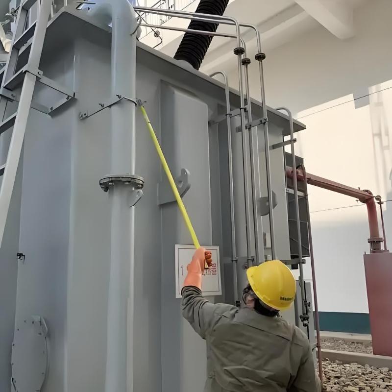
Implementation Steps
1. Safety Preparation
Disconnect all external power sources and verify that there is no voltage. Close the grounding switch and hang warning signs. Remove connections unrelated to the test, and use dedicated shorting wires to short-circuit the three phases A/B/C of the circuit breaker.
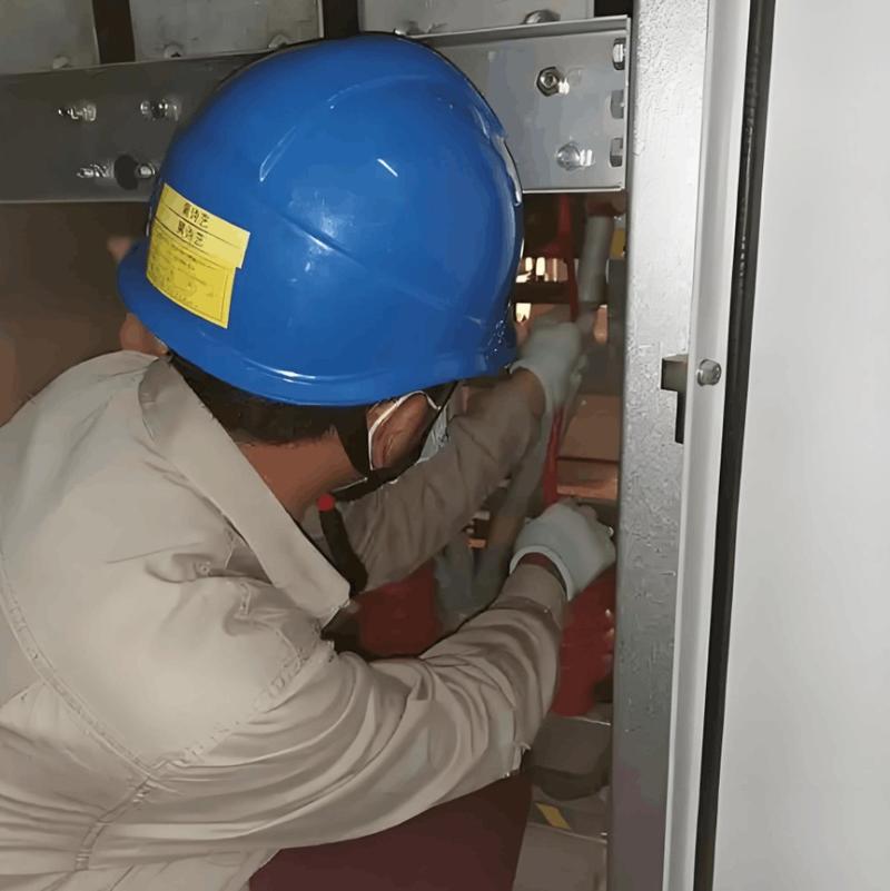
2. Wiring Method
Connect the high-voltage terminal of the withstand voltage tester to the main circuit terminals of the circuit breaker, and connect the grounding terminal to the grounding bolt on the circuit breaker's enclosure. For secondary circuit testing, use insulating tape to cover exposed contacts, and clamp the high-voltage output lead of the tester to the secondary terminal block.
3. Voltage Rising Process
Raise the voltage at a rate of 1kV per second to the specified voltage value, during which observe changes in leakage current. After the voltage stabilizes, start timing. After the specified time has elapsed, reduce the voltage uniformly to zero. If abnormal discharge sounds, sudden current changes, or insulation gas leakage occur during the test, immediately terminate the test.
4. Result Judgment
The test is considered qualified if the leakage current does not exceed 100μA during the test and no breakdown or flashover occurs. Record the initial voltage value, peak leakage current, ambient temperature and humidity data, and perform trend comparison analysis with historical data.
Precautions
The test voltage must be corrected when altitude exceeds 100m
Equipment that has just been taken out of service must be left stationary for 30 minutes to dissipate heat
GIS combined electrical equipment requires overall testing
Testing is prohibited when internal gas pressure is abnormal
Operators must wear high-voltage insulating boots and protective goggles
Common Problem Handling
Obvious discharge sound but no breakdown: Check whether the vacuum degree of the arc extinguishing chamber is below 6.6×10⁻²Pa; replace the vacuum interrupter if necessary.
Excessive leakage current: Check whether there are tracking marks on the insulating pull rod; clean dirt from the porcelain insulator surface and retest.
Local overheating: Suspend the test and investigate issues such as oxidation on contact surfaces or insufficient spring pressure.
After the test is completed, restore the equipment to its original state, clean the work site, and enter the test data into the equipment operation and maintenance file for reference during the next maintenance. The recommended periodic test cycle is: perform the first test one year after new equipment is put into operation, subsequent tests every 3 years, and for equipment that has been in operation for more than 15 years, shorten the interval to every 2 years.