How to Correctly Calculate SST Transformer kVA Capacity?

ransformer Capacity Selection: Ensuring Reliable and Efficient Power System Operation
Transformer capacity refers to the apparent power at the transformer’s main tap position. The value indicated on the nameplate is known as the rated capacity, typically expressed in kilovolt-amperes (kVA). In practical operation, improperly sized transformers can lead to either under-loading (due to oversizing) or overloading/overcurrent conditions, which may result in equipment overheating, reduced efficiency, and even catastrophic failure. These mismatches directly compromise the reliability and economic efficiency of electrical power systems. Therefore, selecting the correct transformer capacity is critical for safe, stable, and cost-effective operation.
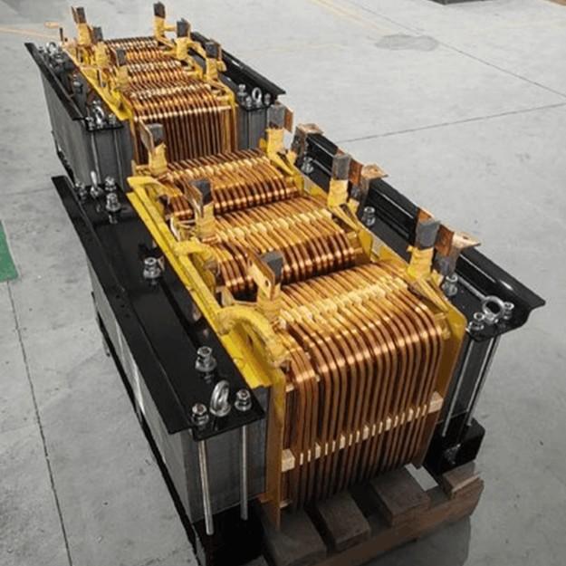
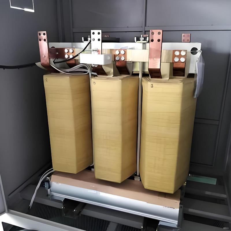
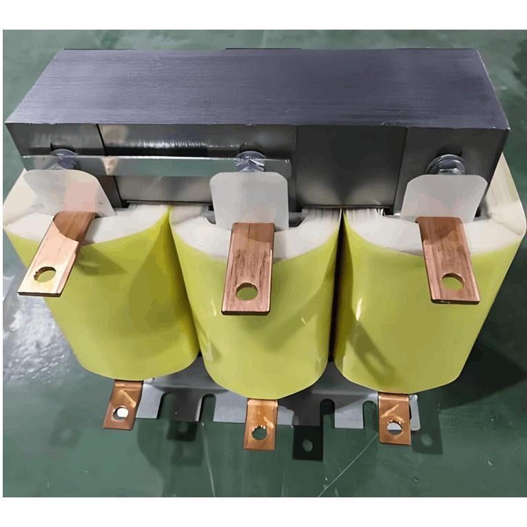
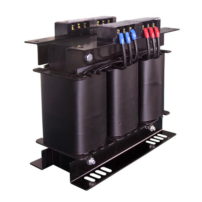
Capacity Calculation for Solid-State Transformers (SSTs)
While the fundamental principles of capacity sizing apply to both conventional and solid-state transformers, the unique architecture of solid-state transformers—integrating power electronics with high-frequency magnetic components—requires careful consideration of additional parameters.
Key factors in SST capacity determination include:
Input Voltage: The voltage supplied to the transformer (e.g., 220V–460V AC). The SST must be compatible with the system’s input voltage range.
Output Voltage: The desired output voltage level (e.g., 80VAC–480VAC), which should match the load requirements.
Rated Capacity: The maximum continuous load the transformer can support, specified in kVA. This must be selected based on peak and continuous load demands.
Input Power: The active power input, calculated as Input Voltage × Input Current, usually expressed in kilowatts (kW).
Given these parameters, the basic formula for calculating apparent power (capacity) is:

Three-Phase Transformer Capacity Calculation (Step-by-Step Example)
Although single-phase and three-phase transformers follow similar principles, this section illustrates the process using a three-phase system.
Step 1: Determine Maximum Single-Phase Load
Calculate the total load on each phase (A, B, and C) independently:
Phase A: 10 kW
Phase B: 9 kW
Phase C: 11 kW
Select the highest phase load: 11 kW (Phase C)
Guideline:
For single-phase loads: Use the nameplate-rated maximum power.
For three-phase loads: Divide the total equipment power by 3 to obtain per-phase contribution.
Example: Phase C load = (300W × 10 computers) + (2kW × 4 air conditioners) = 3kW + 8kW = 11kW
Step 2: Calculate Equivalent Three-Phase Active Power
To ensure balanced loading, multiply the maximum single-phase power by 3:

This represents the equivalent three-phase active power.
Step 3: Convert Active Power to Apparent Power (kVA)
Most transformers are rated at a power factor (PF) of 0.8. To determine the required apparent power:

Step 4: Apply Load Factor for Optimal Sizing
According to the Electrical Engineering Design Manual, for a single transformer serving a steady load, the optimal load factor (β) is approximately 85% (typically 80%–90%). This ensures efficient operation while allowing margin for load fluctuations.
Using the formula:

Where:
S: Calculated apparent power (41.25 kVA)
Se: Required transformer rated capacity
β: Load factor (0.85)

Referring to standard transformer ratings (e.g., 50, 63, 80 kVA), the next available standard size is 50 kVA.
Final Considerations
Accurate transformer sizing prevents both inefficiency and risk:
Oversizing leads to low loading, reduced efficiency, and higher capital cost.
Undersizing causes overheating, insulation degradation, and shortened lifespan.
For solid-state transformers, additional factors such as harmonic content, transient loads, cooling requirements, and control flexibility must also be evaluated during selection.
By following a structured approach—load assessment, per-phase analysis, power factor correction, and application of standard load factors—engineers can ensure optimal transformer selection for reliable, economical, and future-ready power systems.