
Energia solar, ut fontem purum et renovabilem, est clavis novae energiae in China. Habet abundantiam theoricam (annuatim 17,000 billionum tonnorum aequivalentis carbonis standard) et magnam potentiam developmenti. Photovoltaica generatio, quae olim operabatur praecipue extra rete in regionibus remotis, nunc rapiditer evolvitur ad photovoltaica integrata in aedificiis et projecta desertalia magnum rete connectentia.
Hoc opus analysat transformatores split-winding in stationibus photovoltaicis rete connectentibus per analysis theoreticas et casus ingeniorum.
1 Principales Characteres Circuiti Principalis Stationum Photovoltaicarum Rete Connectentium
Circuitus principalis stationum photovoltaicarum stricte coniunctus est cum dispositionibus inverter: inverter distributae aptae sunt pro projectis integratis in aedificiis, dum inverter centralizatae praefertae sunt pro stationibus photovoltaicis desertalibus (ad efficaciam generationis optimam sub illuminatione uniformi via centralizati Maximum Power Point Tracking - MPPT).
Tamen, plus catenarum vel maior capacitas inverter non semper utilitas—distances cabling, deminutio voltage, et ratio pretii versus performance consideranda sunt. Itaque, longitudines cabling ab catenis ad combiner boxes ad inverter et areas photovoltaic blocks determinantur per rationes reditus investimenti. Pro optimisatione economico, capacitas inverter centralizatorum typice inter 500 kW et 630 kW variat.
Stationes photovoltaicae rete connectentes principale tria schemata circuiti principalis adoptant (ut ostenditur in Figura 1). Schema unius catenae (cum transformatoribus step-up) est simplex sed multos transformatores requirit. Schema magni unitatis (incorporans transformatores step-up) est designum mainstream, effective balancens costum et efficaciam.
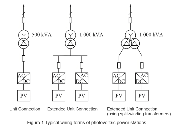
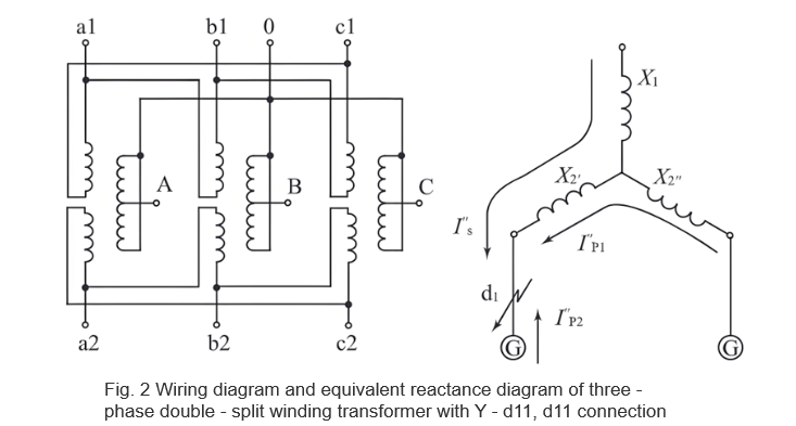
Hoc opus discutit advantages usus transformatorum split-winding pro wiring unitatis expanderunt. Comparata ad communes transformatores double-winding, una phase double-split winding transformer constat unius high-voltage winding et duobus low-voltage windings. Low-voltage windings habent eundem voltage et capacitem sed tantum magnetica copulatio tenuis inter eos, ut ostenditur in Figura 2.
Hic transformer typice tres modos operationis habet: through operation, half-through operation, et split operation. Quando plures rami split winding paralleli sunt in totum low-voltage winding contra high-voltage winding, vocatur through operation, et impedimentum circuitus brevis-circuitus transformer vocatur through impedance X1 - 2. Quando unus ramus low-voltage split winding contra high-voltage winding operatur, vocatur half-through operation, et impedimentum circuitus brevis-circuitus vocatur half-through impedance X1 - 2'. Quando unus ramus split winding contra alium ramum operatur, vocatur split operation, et impedimentum circuitus brevis-circuitus vocatur split impedance X2 - 2'.
2 Advantages Transformatorum Split-Winding
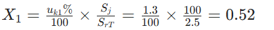
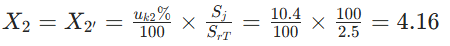
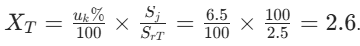
Pro faciliore disceptatione, parametri technici producti maturi citantur pro comparatione quantitativa cum communibus transformatoribus double-winding. Sume 2500 kVA split-winding transformer: 37 ± 2×2.5% / 0.36 kV / 0.36 kV, 50 Hz, percentuale reactance brevis-circuitus 6.5%, full-through reactance percentage 6.5%, half-through reactance percentage 11.7%, split coefficient < 3.6%.Calculations dant:
Full-through reactance: X1 - 2 = X1 + X2 // X2
Half-through reactance: X1 - 2' = X1 + X2
Per-unit values:
High-voltage side branch reactance:
Low-voltage side branch reactance:
2.1 Reducendo Currentem Brevis-Circuitus
Durante brevis-circuitus in d1 in Figura 2, currentis brevis-circuitus tres componentes habet: a systemate (high-voltage side, cum componentibus periodicis non-decrescentibus), non-fault branch I''p1, et fault branch I''p2. Pro circuit-breaker low-voltage in fault branch, sua capacitas breaking considerat summa currentis systematis et non-fault branch. Cum split-winding transformer:
System-supplied short-circuit current:

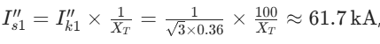
Inverter-type distributed power short-circuit current est 2–4 times rated current (duration 1.2–5 ms, 0.06–0.25 cycles), et non-fault branch current est ~4 kA. Pro communi double-winding transformer (pro comparabilitate, assume uk% = 6.5, idem ut full-through reactance percentage split-winding transformer uk1 - 2%:
The per-unit reactance is:
The system-supplied short-circuit current is:
with additional contributions from non-fault branches. Clearly, using split-winding transformers for expanded-unit wiring significantly reduces the breaking-capacity requirement for low-voltage side branch circuit breakers.
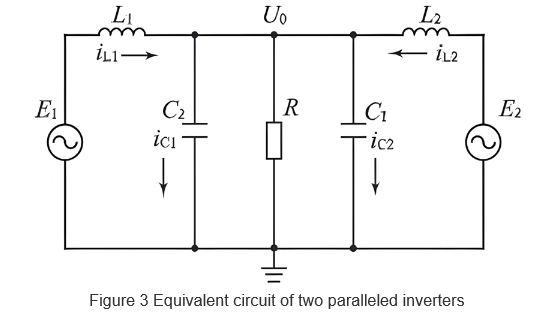
Assume that the parameters of the parallel modules are completely the same and the MPPT control parameters of the inverters are the same. Then, C1 = C2 = C, L1 = L2 = L, and the inductor current of each inverter is:

It can be seen that the inductor current of each inverter consists of two parts: The first is the load current, which is the same for both inverters; the second is the circulating current, related to the amplitude, phase, and frequency differences of the inverters’ output voltages.
Currently, the main control logic for inverters in PV power stations is Maximum Power Point Tracking (MPPT). Solar cell modules have internal and external resistances. When MPPT control makes these resistances equal at a certain moment, the PV module operates at the maximum power point. Taking Figure 3 as an example, the active power P1 and reactive power Q1 output by Inverter 1 are:

2.3 Maintaining Voltage of Non-Fault Branches
Taking Figures 2 and 3 as examples, photovoltaic power stations usually adopt a centralized inverter-transformer layout, and the cable impedance between the inverter and transformer is negligible. With an ordinary double-winding transformer, the voltage of the non-fault branch drops to zero potential. In this case, relay protection is generally used to delay the operation of the non-fault branch circuit breaker to reduce the fault removal range. However, this method may not meet the protection requirements for photovoltaic power stations. If the removal time of the fault branch exceeds the low-voltage ride-through capability of the inverter, the non-fault branch will be forced to disconnect from the grid, increasing the risk of expanding the fault range.
With a split-winding transformer, due to the existence of split impedance, the short-circuit current provided by the system is equivalent to operating in the half-through mode of the split-winding transformer. The short-circuit current supplied by the non-fault branch inverter is equivalent to the split operation mode of the split-winding transformer. At the moment of short-circuit, the output voltage U''2 of the non-fault branch inverter is I''s × X'2 + I''p2 × (X''2 + X'''2). Since the high-voltage side is an infinite system, according to the previous discussion, I''s is much larger than I''p2. Therefore, the first part I''s × X'2 does not decay and is larger than the second part I''p2 × (X''2 + X'''2).
Calculations show that . The output voltage of the non-fault branch inverter can be maintained at least at about 0.5Un. According to the low-voltage ride-through requirements of the photovoltaic power station, the removal time is greater than 1 s (50 cycles). Thus, the expanded-unit wiring with split-winding transformers can reliably meet the requirement that the non-fault branch does not disconnect from the grid within the removal time of the fault branch circuit breaker.
3 Conclusion
Split-winding transformers are widely used in engineering, especially suitable for grid-connected photovoltaic power stations. As discussed above, their advantages mainly lie in reducing short-circuit current, restricting operating circulating current, and maintaining the voltage of non-fault branches. Based on engineering design examples, this paper theoretically analyzes their application advantages in photovoltaic power stations, providing certain guiding significance for the selection of wiring forms and equipment in grid-connected photovoltaic power station projects.


