
Nûrî energy, wekî yek avdana û tevzîya taybetand, yek sereke xweyên nû yên di Çinê de dest pê kirin. Li ser bîra derya (17,000 milyar ton standart koyeq da) û potensiyel çêdker baz bi tevahîda. Rêbazên photovoltaic, ku lehê yekem di navçeyên derengên demgeha berfînan de hatîne veqetand, niha piştre jî vê zanîna ji bo projeyên bina-integrated û projeyên grid-connected ên mezin di navçeyên çolperdeh de.
Navenda wan dikarin split-winding transformers di statyonên grid-connected photovoltaic de li ser analîza teorî û serxwebûnên inzhenerî.
1 Xezanên Serxwebûnê ya Bêtirin Statyonên Grid-Connected Photovoltaic
Xezanên bêtirin statyonên photovoltaic bi rêbazên inverterên nîşan didin: inverterên parastîn ji bo projeyên bina-integrated biçare, lê inverterên centralî ji bo statyonên photovoltaic ên çolperdeh (ji bo hewalata optimal power generation efficiency di ronîna uniform de bi central Maximum Power Point Tracking - MPPT).
Lê, pirseriya string û inverterên mezin nekî na her dem bêzindî ye - deraqêta kabl, drop voltage û cost-performance pêdivsaz dibin. Demên, deraqêta kablên ji stringên bi combiner boxên ji bo inverter û herêmên photovoltaic bi rêbazên investîment-return ratio name. Ji bo optimizasyona ekonomî, kapasiteya inverterên centralî bi cerabî 500 kW ji 630 kW re hatine destnîşan kirin.
Statyonên grid-connected photovoltaic yekêmtirîn têrîfên têrîfên serxwebûn (wagire şekil 1). Şekila single-string (bi step-up transformers) ezmûn û basit e, lê hejmarên zorî transformeran din. Şekila large-unit (di navça step-up transformers de) dizaynê mainstream e, kişîna cost û efektivîteya bi tevahîda.
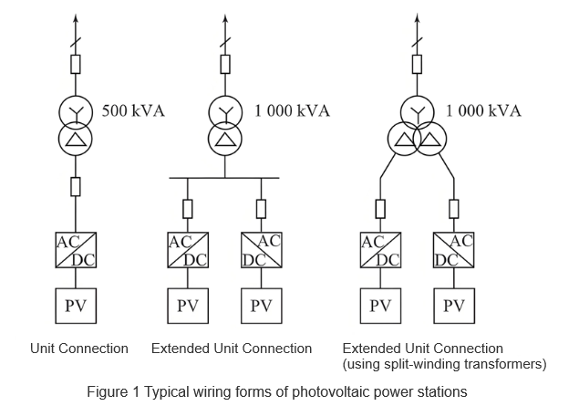
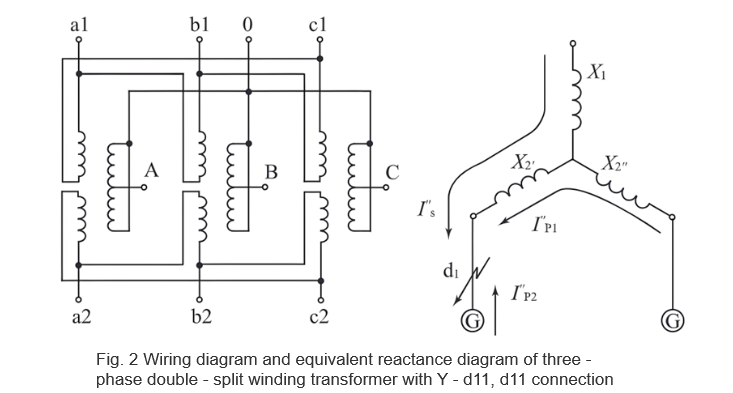
Navenda wan dikarin avantajên bikaranîna split-winding transformers ji bo expanded-unit wiring. Pirsgirêka double-winding transformers, her phase ya double-split winding transformer yek high-voltage winding û du low-voltage windings hatine. Low-voltage windings bi tensîon û kapasiteyek same, lê bi magnetic coupling weak an û bi navbera wan, wagire şekil 2.
Transformera wê bi têrîfên têrîfên têrîfên têrîfên têrîfên têrîfên têrîfên têrîfên têrîfên têrîfên têrîfên têrîfên têrîfên têrîfên têrîfên têrîfên têrîfên têrîfên têrîfên têrîfên têrîfên têrîfên têrîfên têrîfên têrîfên têrîfên têrîfên têrîfên têrîfên têrîfên têrîfên têrîfên têrîfên têrîfên têrîfên têrîfên têrîfên têrîfên têrîfên têrîfên têrîfên têrîfên têrîfên têrîfên têrîfên têrîfên têrîfên têrîfên têrîfên têrîfên têrîfên têrîfên têrîfên têrîfên têrîfên têrîfên têrîfên têrîfên têrîfên têrîfên têrîfên têrîfên têrîfên têrîfên têrîfên têrîfên têrîfên têrîfên têrîfên têrîfên têrîfên têrîfên têrîfên têrîfên têrîfên têrîfên têrîfên têrîfên têrîfên têrîfên têrîfên têrîfên têrîfên têrîfên têrîfên t......
2 Avantajên Split-Winding Transformers
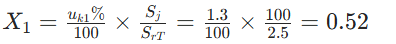
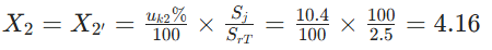
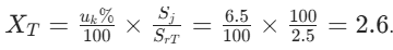
Ji bo pêşkêşkirina wan, parametreyên teknîkên pirûzên naverokan hatine bikaranîn ji bo parastîna bi double-winding transformers. Ji bo transformer split-winding 2500 kVA: 37 ± 2×2.5% / 0.36 kV / 0.36 kV, 50 Hz, short-circuit reactance percentage 6.5%, full-through reactance percentage 6.5%, half-through reactance percentage 11.7%, split coefficient < 3.6%. Hesabkirin:
Full-through reactance: X1 - 2 = X1 + X2 // X2
Half-through reactance: X1 - 2' = X1 + X2
Per-unit values:
High-voltage side branch reactance:
Low-voltage side branch reactance:
2.1 Reducing Short-Circuit Current
Di dawitî da ku short-circuit di d1 de di şekil 2 de, short-circuit current gotarên tri ye: ji system (high-voltage side, bi non-decaying periodic components), non-fault branch I''p1, û fault branch I''p2. Ji bo low-voltage circuit breaker di fault branch de, breaking capacity-ya wê bi sum of system û non-fault branch currents name. Bi split-winding transformer:
System-supplied short-circuit current:

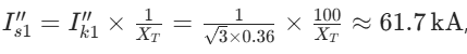
Inverter-type distributed power short-circuit current 2-4 times rated current (duration 1.2-5 ms, 0.06-0.25 cycles), û non-fault branch current ~4 kA. Ji bo ordinary double-winding transformer (ji bo comparability, assume uk% = 6.5, same as the full-through reactance percentage of the split-winding transformer uk1 - 2%:
The per-unit reactance is:
The system-supplied short-circuit current is:
with additional contributions from non-fault branches. Clearly, using split-winding transformers for expanded-unit wiring significantly reduces the breaking-capacity requirement for low-voltage side branch circuit breakers.
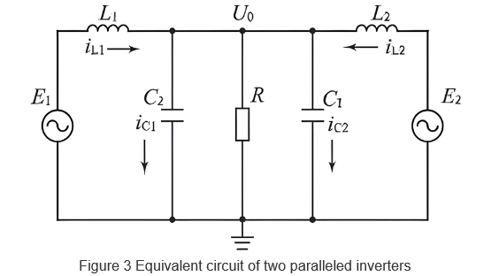
Assume that the parameters of the parallel modules are completely the same and the MPPT control parameters of the inverters are the same. Then, C1 = C2 = C, L1 = L2 = L, and the inductor current of each inverter is:

It can be seen that the inductor current of each inverter consists of two parts: The first is the load current, which is the same for both inverters; the second is the circulating current, related to the amplitude, phase, and frequency differences of the inverters' output voltages.
Currently, the main control logic for inverters in PV power stations is Maximum Power Point Tracking (MPPT). Solar cell modules have internal and external resistances. When MPPT control makes these resistances equal at a certain moment, the PV module operates at the maximum power point. Taking Figure 3 as an example, the active power P1 and reactive power Q1 output by Inverter 1 are:

2.3 Maintaining Voltage of Non-Fault Branches
Taking Figures 2 and 3 as examples, photovoltaic power stations usually adopt a centralized inverter-transformer layout, and the cable impedance between the inverter and transformer is negligible. With an ordinary double-winding transformer, the voltage of the non-fault branch drops to zero potential. In this case, relay protection is generally used to delay the operation of the non-fault branch circuit breaker to reduce the fault removal range. However, this method may not meet the protection requirements for photovoltaic power stations. If the removal time of the fault branch exceeds the low-voltage ride-through capability of the inverter, the non-fault branch will be forced to disconnect from the grid, increasing the risk of expanding the fault range.
With a split-winding transformer, due to the existence of split impedance, the short-circuit current provided by the system is equivalent to operating in the half-through mode of the split-winding transformer. The short-circuit current supplied by the non-fault branch inverter is equivalent to the split operation mode of the split-winding transformer. At the moment of short-circuit, the output voltage U''2 of the non-fault branch inverter is I''s × X'2+ I''p2× (X''2 + X'''2). Since the high-voltage side is an infinite system, according to the previous discussion, I''s is much larger than I''p2. Therefore, the first part I''s × X'2 does not decay and is larger than the second part I''p2 × (X''2 + X'''2).
Calculations show that . The output voltage of the non-fault branch inverter can be maintained at least at about 0.5Un. According to the low-voltage ride-through requirements of the photovoltaic power
station, the removal time is greater than 1 s (50 cycles). Thus, the expanded-unit wiring with split-winding transformers can reliably meet the requirement that the non-fault branch does not disconnect from the grid within the removal time of the fault branch circuit breaker.
3 Conclusion
Split-winding transformers are widely used in engineering, especially suitable for grid-connected photovoltaic power stations. As discussed above, their advantages mainly lie in reducing short-circuit current, restricting operating circulating current, and maintaining the voltage of non-fault branches. Based on engineering design examples, this paper theoretically analyzes their application advantages in photovoltaic power stations, providing certain guiding significance for the selection of wiring forms and equipment in grid-connected photovoltaic power station projects.


