
Ang enerhiya sa solar, isip usa ka malinis ug renewable nga mapagkukunan sa enerhiya, usa ka key nga bag-ong enerhiya nga gisupportan sa China. Adunay kini abudante nga teorikal nga impormasyon (17,000 billion tons of standard coal equivalent annually) ug dako nga potensyal sa pag-develop. Ang photovoltaic power generation, una nga nag-operate off-grid sa mga remote areas, karon nag-evolve rapido tungod sa building-integrated photovoltaics ug large-scale desert-based grid-connected projects.
Kini nga paper nag-analisa sa split-winding transformers sa grid-connected photovoltaic power stations pinaagi sa teorikal nga analisis ug engineering cases.
1 Main Circuit Features of Grid-Connected Photovoltaic Power Stations
Ang main circuit sa photovoltaic power stations labi nga adunay relasyon sa inverter layouts: ang distributed inverters ang mas maayo para sa building-integrated projects, samtang ang centralized inverters ang preferred para sa desert photovoltaic power stations (aroon sa optimal power generation efficiency under uniform illumination via centralized Maximum Power Point Tracking - MPPT).
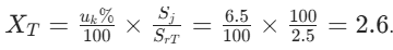
Pero wala gyud tanang mas daghan nga strings o mas dako nga capacity sa inverters beneficial—ang cable distance, voltage drop, ug cost-performance kinahanglan mosabot. Busa, ang cable lengths gikan sa strings hangtod sa combiner boxes hangtod sa inverters ug ang areas sa photovoltaic blocks determinado sa investment-return ratios. Para sa economic optimization, ang capacity sa centralized inverters tipikal nga naka-range gikan 500 kW hangtod 630 kW.
Ang grid-connected photovoltaic power stations pangutana sa tulo ka main circuit schemes (as shown in Figure 1). Ang single-string scheme (with step-up transformers) simple pero nginahanglan og dako nga numero sa transformers. Ang large-unit scheme (incorporating step-up transformers) ang mainstream design, balancing cost ug efficiency effectively.
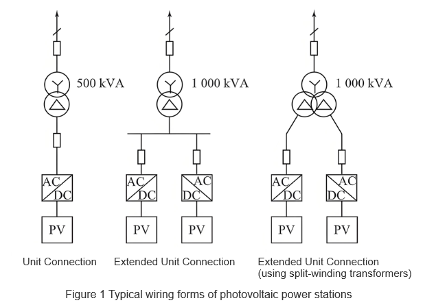
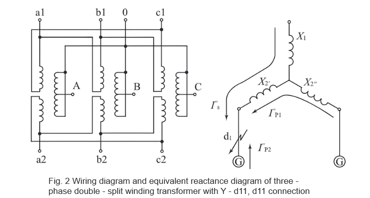
Kini nga paper nagdiskubre sa advantages sa paggamit og split-winding transformers alang sa expanded-unit wiring. Kumpara sa ordinary double-winding transformers, ang bawat phase sa double-split winding transformer gisakop sa usa ka high-voltage winding ug duha ka low-voltage windings. Ang low-voltage windings adunay parehas nga voltage ug capacity apan lang gamay nga magnetic coupling gituyo, as shown in Figure 2.
Kini nga transformer tipikal nga adunay tulo ka operating modes: through operation, half-through operation, ug split operation. Kon ilang branches sa split winding parallelon sa total low-voltage winding aron magoperate kontra sa high-voltage winding, kini gitawag og through operation, ug ang short-circuit impedance gitawag og through impedance X1 - 2. Kon usa ka branch sa low-voltage split winding magoperate kontra sa high-voltage winding, kini gitawag og half-through operation, ug ang short-circuit impedance gitawag og half-through impedance X1 - 2'. Kon usa ka branch sa split winding magoperate kontra sa uban pa, kini gitawag og split operation, ug ang short-circuit impedance gitawag og split impedance X2 - 2'.
2 Advantages of Split-Winding Transformers
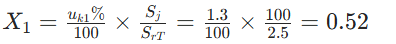
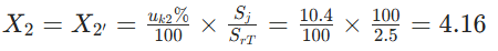
Para mas sayon ang diskusyon, gisangpot ang teknikal nga parameters sa mature products aron quantitative comparison sa ordinary double-winding transformers. Tandaan ang 2500 kVA split-winding transformer: 37 ± 2×2.5% / 0.36 kV / 0.36 kV, 50 Hz, short-circuit reactance percentage 6.5%, full-through reactance percentage 6.5%, half-through reactance percentage 11.7%, split coefficient < 3.6%.Calculations give:
Full-through reactance: X1 - 2 = X1 + X2 // X2
Half-through reactance: X1 - 2' = X1 + X2
Per-unit values:
High-voltage side branch reactance:
Low-voltage side branch reactance:
2.1 Reducing Short-Circuit Current
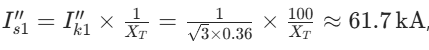
Durante sa short-circuit sa d1 sa Figure 2, ang short-circuit current adunay tulo ka components: gikan sa system (high-voltage side, with non-decaying periodic components), non-fault branch I''p1, ug fault branch I''p2. Para sa low-voltage circuit breaker sa fault branch, ang iyang breaking capacity considera ang sum sa system ug non-fault branch currents.With a split-winding transformer:
System-supplied short-circuit current:

Inverter-type distributed power short-circuit current 2–4 times the rated current (duration 1.2–5 ms, 0.06–0.25 cycles), ug ang non-fault branch current ~4 kA.For an ordinary double-winding transformer (for comparability, assume uk% = 6.5, same as the full-through reactance percentage of the split-winding transformer uk1 - 2%:
The per-unit reactance is:
The system-supplied short-circuit current is:
with additional contributions from non-fault branches.Clearly, using split-winding transformers for expanded-unit wiring significantly reduces the breaking-capacity requirement for low-voltage side branch circuit breakers.
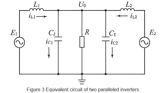
Assume that the parameters of the parallel modules are completely the same and the MPPT control parameters of the inverters are the same. Then, C1 = C2 = C, L1 = L2 = L, and the inductor current of each inverter is:

It can be seen that the inductor current of each inverter consists of two parts: The first is the load current, which is the same for both inverters; the second is the circulating current, related to the amplitude, phase, and frequency differences of the inverters’ output voltages.
Currently, the main control logic for inverters in PV power stations is Maximum Power Point Tracking (MPPT). Solar cell modules have internal and external resistances. When MPPT control makes these resistances equal at a certain moment, the PV module operates at the maximum power point. Taking Figure 3 as an example, the active power P1 and reactive power Q1 output by Inverter 1 are:

2.3 Maintaining Voltage of Non-Fault Branches
Taking Figures 2 and 3 as examples, photovoltaic power stations usually adopt a centralized inverter-transformer layout, and the cable impedance between the inverter and transformer is negligible. With an ordinary double-winding transformer, the voltage of the non-fault branch drops to zero potential. In this case, relay protection is generally used to delay the operation of the non-fault branch circuit breaker to reduce the fault removal range. However, this method may not meet the protection requirements for photovoltaic power stations. If the removal time of the fault branch exceeds the low-voltage ride-through capability of the inverter, the non-fault branch will be forced to disconnect from the grid, increasing the risk of expanding the fault range.
With a split-winding transformer, due to the existence of split impedance, the short-circuit current provided by the system is equivalent to operating in the half-through mode of the split-winding transformer. The short-circuit current supplied by the non-fault branch inverter is equivalent to the split operation mode of the split-winding transformer. At the moment of short-circuit, the output voltage U''2 of the non-fault branch inverter is I''s × X'2+ I''p2× (X''2 + X'''2). Since the high-voltage side is an infinite system, according to the previous discussion, I''s is much larger than I''p2. Therefore, the first part I''s × X'2 does not decay and is larger than the second part I''p2 × (X''2 + X'''2).
Calculations show that . The output voltage of the non-fault branch inverter can be maintained at least at about 0.5Un. According to the low-voltage ride-through requirements of the photovoltaic power
station, the removal time is greater than 1 s (50 cycles). Thus, the expanded-unit wiring with split-winding transformers can reliably meet the requirement that the non-fault branch does not disconnect from the grid within the removal time of the fault branch circuit breaker.
3 Conclusion
Split-winding transformers are widely used in engineering, especially suitable for grid-connected photovoltaic power stations. As discussed above, their advantages mainly lie in reducing short-circuit current, restricting operating circulating current, and maintaining the voltage of non-fault branches. Based on engineering design examples, this paper theoretically analyzes their application advantages in photovoltaic power stations, providing certain guiding significance for the selection of wiring forms and equipment in grid-connected photovoltaic power station projects.


