• Product
  • Suppliers
  • Manufacturers
  • Solutions
  • Free tools
  • Knowledges
  • Experts
  • Communities
Search


Prototype Development of 20 kV Single-Phase Distribution Transformer

Dyson
Dyson
Field: Electrical Standards
China

1. Design of 20 kV Single - phase Distribution Transformer

20 kV distribution systems usually adopt cable lines or mixed cable - overhead line networks, and the neutral point is mostly grounded through a small resistance. When a single - phase grounding occurs, there will be no problem that the phase voltage will rise by more than √3 times as in the case of a single - phase fault in a 10 kV system. Therefore, the single - phase distribution transformer of the 20 kV system can adopt the type of grounding the end of the coil. This can reduce the main insulation of the single - phase distribution transformer, making the volume and cost of the 20 kV single - phase distribution transformer not much different from those of the 10 kV one.

2. Selection of Impulse and Test Voltages

For the basic impulse level (BIL) and insulation test level of the 20 kV single - phase distribution transformer, considerations are as follows:

The American National Standard ANSI C57.12.00—1973 (IEEE Std 462—1972) stipulates that the basic impulse level (BIL) of the high - voltage side (20 kV) is 125 kV; the rated voltage of the high - voltage component is 15.2 kV, and the AC withstand voltage (60 Hz/min) is 40 kV.

The insulation test stipulates that the applied voltage test is not required, but the induced voltage test must be carried out. During the test, after applying a voltage to the outgoing terminal of one winding, the voltage of each high - voltage outgoing terminal to the ground reaches 1 kV plus 3.46 times the rated voltage of the transformer winding. That is, in the induction test (frequency - doubled and voltage - doubled test), the high - voltage is:

2.1 Low-voltage Side (240/120 V)

  • Basic Impulse Level (BIL): 30 kV

  • AC Withstand Voltage (60 Hz/min): 10 kV

2.2 According to China’s National Transformer Quality Supervision Test Regulations

  • High-voltage side:

    • Basic Impulse Level (BIL): 125 kV (full wave), 140 kV (chopped wave)

    • AC Induced Withstand Voltage (200 Hz/min): 40 kV

  • Low-voltage side:

    • Applied Voltage (50 Hz/min): 4 kV

3. Structure and Features of 20 kV Single-phase Distribution Transformers

Two specifications (50 kVA and 80 kVA) were prototyped, both adopting an outer - iron structure. To reduce main insulation, an end - insulation structure was added. A single bushing is used for lead - out. The end of the high - voltage coil is grounded and connected to the tank. The low - voltage winding is a single - coil structure.

3.1Technical Performance Comparison Between Prototyped 20 kV and 10 kV Single-phase Distribution Transformers

  • Loss comparison between 20 kV and 10 kV (taking 50 kVA and 80 kVA as examples) is shown in Table 1.

  • Weight comparison between 20 kV and 10 kV (taking 50 kVA and 80 kVA as examples) is shown in Table 2.

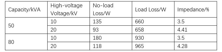
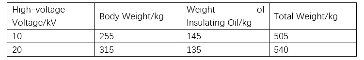
4. 20 kV∥10 kV Single - phase Dual - voltage Distribution Transformer

Upgrading a 10 kV to a 20 kV distribution system involves replacing key equipment like distribution transformers. High - cost replacements and power outages disrupting production make designing a dual - voltage (10 kV/20 kV) single - phase transformer a solution to ease these issues.

4.1 Design

Based on the 10 kV wound - core single - phase distribution transformer, this dual - voltage variant leverages the 20 kV = 2×10 kV relationship, using series - parallel primary coils. With two parallel high - voltage coils, two core columns get high - voltage/low - voltage windings (high - voltage coils parallel). Two low - voltage coils series at the “mid - point” output ±220 V - ground for two users. Let W1 (high - voltage turns) and W2 (low - voltage turns). In parallel, U1/U2 = W1/W2 = 10 kV/220V, and total high - voltage current doubles a single coil’s. In series, high - voltage input current equals coil current.

4.2 Switching Application

Capacity stays consistent for 20 kV or 10 kV high - voltage inputs. At 20 kV input, two high - voltage coils in series mean each bears 10 kV. With high - voltage current I1, capacity S1 = I1×20 = 20I1(kVA). Switched to 10 kV, parallel high - voltage coils give 2I1 input current, so S1 = 2I1×10 = 20I1 (kVA). Thus, S1 = S2).

4.3 Structure

  • Structure matches the single - phase wound - core transformer (patent No. 4612429).

  • 10 kV/20 kV voltage - switching uses a reliable contact strip tap - changer.

  • Insulation meets IEC 20 kV transformer standards (rated impulse voltage: 125 kV).

  • Noise complies with IEC and relevant power company technical specs.

4.4 Advantages of Single - phase Dual - voltage Transformer

  • Energy Conservation:The line loss of the 20 kV distribution system is 25% of that of the 10 kV distribution system, achieving a 75% energy savings. By adopting the single - phase wound - core technology in this design, the no - load loss of the transformer is 30% lower than that of the currently used S11 - type distribution transformer.

  • Construction Cost Savings:During the upgrade from 10 kV to 20 kV, only a changeover switch is needed to switch the voltage. This reduces the power outage time, and the entire operation process can be completed within just a few minutes.

5. Conclusion

  • Most neutral points of the 20 kV system are grounded through a small - resistance system. Therefore, it is easier to handle the main insulation of single - phase transformers at the 20 kV level compared to the 10 kV level.

  • The load loss of 20 kV - class single - phase transformers is at the same level as that of 10 kV - class ones; their weight is also at a comparable level. In terms of no - load loss, 20 kV is lower than 10 kV. Regarding impedance, the 20 kV single - phase transformer is 20% higher than the 10 kV one.

  • The 20 kV single - phase transformer is relatively economical. Its price will not differ significantly from that of 10 kV - class single - phase transformers.

  • The 20 kV∥10 kV single - phase dual - voltage distribution transformer can be used in both 10 kV and 20 kV distribution systems. When upgrading a 10 kV system to a 20 kV system, there is no need to replace the transformer; simply switching the changeover switch suffices. It is a relatively economical and convenient method.

Give a tip and encourage the author!
Recommended
Minimum Operating Voltage for Vacuum Circuit Breakers
Minimum Operating Voltage for Trip and Close Operations in Vacuum Circuit Breakers1. IntroductionWhen you hear the term "vacuum circuit breaker," it might sound unfamiliar. But if we say "circuit breaker" or "power switch," most people will know what it means. In fact, vacuum circuit breakers are key components in modern power systems, responsible for protecting circuits from damage. Today, let's explore an important concept — the minimum operating voltage for trip and close operations.Though it
Dyson
10/18/2025
Efficient Wind-PV Hybrid System Optimization with Storage
1. Analysis of Wind and Solar Photovoltaic Power Generation CharacteristicsAnalyzing the characteristics of wind and solar photovoltaic (PV) power generation is fundamental to designing a complementary hybrid system. Statistical analysis of annual wind speed and solar irradiance data for a specific region reveals that wind resources exhibit seasonal variation, with higher wind speeds in winter and spring and lower speeds in summer and autumn. Wind power generation is proportional to the cube of
Dyson
10/15/2025
Wind-Solar Hybrid Powered IoT System for Real-Time Water Pipeline Monitoring
I. Current Status and Existing ProblemsCurrently, water supply companies have extensive networks of water pipelines laid underground across urban and rural areas. Real-time monitoring of pipeline operation data is essential for effective command and control of water production and distribution. As a result, numerous data monitoring stations must be established along the pipelines. However, stable and reliable power sources near these pipelines are rarely available. Even when power is accessible,
Dyson
10/14/2025
How to Build an AGV-Based Intelligent Warehouse System
Intelligent Warehouse Logistics System Based on AGVWith the rapid development of the logistics industry, growing land scarcity, and rising labor costs, warehouses—serving as key logistics hubs—are facing significant challenges. As warehouses become larger, operational frequencies increase, information complexity grows, and order-picking tasks become more demanding, achieving low error rates and reduced labor costs while improving overall storage efficiency has become a primary goal for the wareh
Dyson
10/08/2025
Send inquiry
Download
Get the IEE Business Application
Use the IEE-Business app to find equipment, obtain solutions, connect with experts, and participate in industry collaboration anytime, anywhere—fully supporting the development of your power projects and business.