SF6 Ring Main Units (RMUs): Current Power Supply Methods, Development Prospects, Advantages Over Metal-Clad Switchgear and Conclusions

Current Power Supply Method Using SF6 Ring Main Units
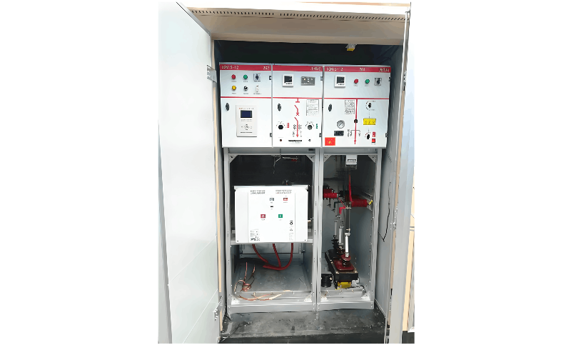
To enhance grid performance, the design of traditional SF6 ring main units (RMUs) has been further optimized. A key feature of second-generation SF6 RMUs is the use of a grounded, enclosed epoxy resin housing, with SF6 gas as the insulating medium. Two three-position load switches and one three-position arc-rotating circuit breaker are integrated into a single sealed unit, equipped with a pressure relief safety valve. In the event of arc-quenching failure, the safety valve releases internal pressure from the enclosure, ensuring operator safety in front of the cabinet.
Due to advantages such as fewer moving parts in the system, small sealed gas chamber volume, compact structure, complete functionality, and low cost, these RMUs have been widely used over the past decade and have proven highly stable and safe. By monitoring and remotely controlling several key node RMUs in open-loop distribution networks, users can have power restored within minutes after a fault, significantly reducing fault identification and isolation time and minimizing user power loss.
Development Prospects of the SF6 RMU Power Supply Method
SF6 ring main power supply, as a prototype and initial stage of grid-based power distribution, provides a foundation for achieving higher power supply reliability. "Grid-based" planning, based on urban control detailed planning and aiming to meet high-reliability user demands, represents a new "bottom-up" model for distribution network planning, construction, operation, and management.
Through grid-based planning and transformation, the average utilization rate of distribution equipment can be appropriately increased, and directional transfer capabilities can be established within and between grids, thereby maximizing the support of lower-level grids to upper-level grids. This is significant for scientifically guiding distribution network construction, ensuring reliable power supply, promoting high-quality development of distribution networks, and building a robust and intelligent distribution network characterized by "grid-based layout, refined protection, and convenient access."
II. Advantages of SF6 Insulated RMUs over Metal-Clad Switchgear in "Five Prevention" Interlocks
In power supply systems, "Five Prevention" (preventing erroneous switching, load switching, grounding under voltage, closing with grounding, and entering energized compartments) interlock technology for high-voltage switchgear (specifically air-insulated metal-clad switchgear) has matured and diversified. Methods include microprocessor-based interlocks using pre-programmed sequences, mechanical interlocks, mechanical sequence locks, or combinations thereof. However, some easily overlooked issues still exist in practice:
Misoperation Prevention for Earthing Switches in Incomer Cabinets of Metal-Clad Switchgear
Some metal-clad switchgear have earthing switches in both outgoing and incoming cabinets. Particularly for bottom-fed switchgear, the risk of misoperation of the earthing switch is often neglected. In contrast, SF6 RMUs inherently avoid this issue due to grounding interlocks and logical interlocks on the incoming side.
Misoperation Prevention for Energized Transformer Compartments
In metal-clad switchgear used in containerized substations, the operating power is typically derived from the transformer's low-voltage side. When the transformer compartment is energized, the electromagnetic lock cannot be opened; when the compartment is de-energized, both the voltage presence indicator and the electromagnetic lock lose power, still preventing opening. This requires a release key to manually unlock, creating a safety hazard.
SF6 RMUs replace the electromagnetic lock with a door limit switch. The normally closed contact of this switch is connected in series with the transformer cabinet's trip circuit, powered from the low-voltage side. Once the transformer compartment door is opened, the limit switch activates, immediately triggering a trip to cut off power, effectively preventing entry into energized compartments.
In summary, SF6 RMUs significantly reduce the design complexity of "Five Prevention" interlocks and minimize risks of personal injury caused by oversights or interlock failures in metal-clad switchgear. Combined with the inherent feature that high-voltage live parts are fully enclosed and inaccessible, SF6 RMUs further highlight their superiority in protecting both professional and non-professional maintenance personnel compared to metal-clad switchgear.
III. Operational Advantages of SF6 Insulated RMUs over Metal-Clad Switchgear
Fully Sealed Insulation, Maintenance-Free
All primary live components (e.g., load switches, busbars) of SF6 RMUs are sealed within the SF6 gas chamber, immune to external environmental factors such as humidity, salt fog, and dust. This ensures high reliability and personnel safety, truly achieving maintenance-free operation. Core components can last up to 20 years without maintenance, making them suitable for unattended distribution rooms.
Compact Structure, Space-Saving
SF6 RMUs are compact and space-efficient, with a single cabinet width of only 325mm (696mm for metering cabinets), significantly reducing the footprint in distribution rooms and making them ideal for space-constrained locations. Switchgear and enclosures are fully assembled at the factory with lifting lugs, allowing for easy on-site installation by simply positioning the enclosure.
Taking a typical 10kV distribution room project as an example (dual incoming lines, six outgoing lines, bus tie sectioning):
Using KYN28 metal-clad switchgear: 10 units required, each 800mm wide and 1500mm deep, main body area 12㎡; considering operation and maintenance clearance (1500mm front, 600mm rear), additional area 16.8㎡; DC screen area approximately 2㎡; total area approximately 30.2㎡.
Using SF6 RMUs: 9 bays required, each 325mm wide and 750mm deep, main body area 2.20㎡; considering 600mm front maintenance clearance (also serving as inspection passage), additional area 1.75㎡; no additional DC screen needed (self-powered protection devices available); total area approximately 3.95㎡. Compared to metal-clad switchgear, this saves 26.25㎡, demonstrating a significant advantage.
High Protection Rating, Strong Environmental Adaptability
SF6 RMUs feature a fully sealed structure, eliminating the need for heaters and preventing condensation. Cable terminations are waterproof and sealed, allowing operation even when submerged. The stainless steel gas chamber of the switchgear (including fuse bushings) achieves an IP67 protection rating and has successfully passed international tests for 24 hours of energized operation underwater at a depth of 5 meters.
In contrast, metal-clad switchgear is indoor equipment, integrated with circuit breakers. An accident in one unit often affects multiple devices and can even escalate to a substation-wide outage. Recent circuit breaker failures, particularly at 6–35kV levels, are frequently linked to insulation degradation in humid environments, poor sealing, insufficient creepage distance, and inappropriate materials. SF6 RMUs, with their fully enclosed, outdoor-suitable design, naturally avoid these issues and maintain reliable power supply even under harsh conditions such as coastal typhoons and heavy rain, demonstrating far superior environmental adaptability.
Excellent Electrical Performance, High Technical Parameters
Circuit breaker cabinets can achieve short-circuit breaking capacities up to 25kA; load switch mechanical life reaches 5,000 operations, far exceeding the national standard requirement of 2,000 operations.
Conclusion
Ring main units have evolved from initial closed-loop structures to open-loop configurations, progressing through oil-immersed fuse RMUs to today's advanced SF6 fully insulated RMUs. Designs have been continuously optimized, and stability has steadily improved. Compared to metal-clad switchgear, SF6 RMUs offer significant advantages in safety, unattended operation, space saving, harsh environment adaptability, electrical performance, and technical parameters. They are now widely used in municipal, metro, and building power supply systems.


