• Product
  • Suppliers
  • Manufacturers
  • Solutions
  • Free tools
  • Knowledges
  • Experts
  • Communities
Search


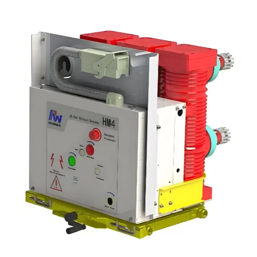
Rockwill HM4 G3 Gas Circuit Breaker: High Gas Tightness Design — Barrier to Leakage Cascade Failures

Rockwill
Field: Manufacturing
10Year<
China

I. Core Proposition: Why High Gas Tightness Is the "Lifeline" of G3 Gas Circuit Breakers

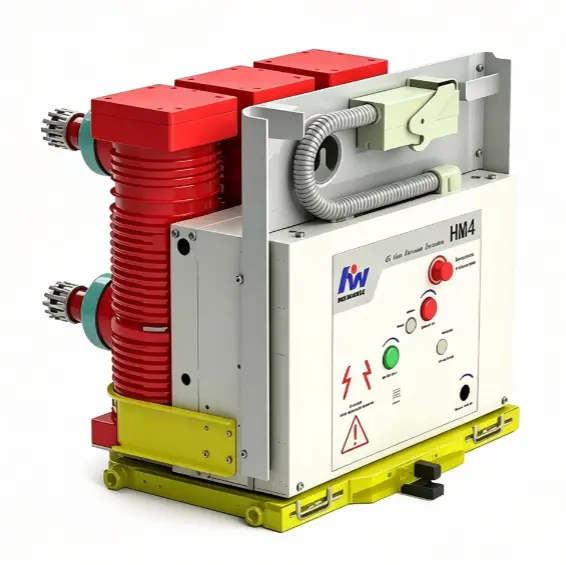
The Rockwill HM4 circuit breaker uses G3 eco-friendly gas to perform both insulation and arc-quenching functions in a single medium. Compared with traditional equipment, its "lifetime maintenance-free" positioning means that gas tightness is not merely a compliance requirement under GB/T 11023-2018  — it is the fundamental physical prerequisite for safe equipment operation throughout its entire lifecycle. The core barriers of high gas tightness requirements are reflected in four dimensions:

iee-business

Strong Physical Correlation with Insulation Strength

The dielectric strength of G3 gas mixtures is strongly positively correlated with gas density (absolute pressure).The HM4 is designed with a rated absolute pressure (e.g., 380 kPa / 450 kPa) as the baseline for the internal electric field of the pole.

Once leakage causes pressure to drop, the electric field within the compact pole becomes distorted, easily triggering partial discharge or creeping flashover.Normal-pressure air cannot replace G3 to meet medium-voltage insulation requirements.

Rigid Dependence of Self-Blast Arc-Quenching Mechanism

The HM4 is equipped with self-blast arc-quenching technology. During opening, the moving contact compresses the sealed gas chamber to form a directed high-speed gas flow that ablates the arc. If the gas chamber leaks, the gas flow velocity decreases, weakening G3's cooling and deionization capability, creating a risk of arc-quenching failure under short-circuit conditions.

Irreversible Damage from Moisture Ingress

According to DL/T 596 , the moisture content in gas chambers connected to the arc extinguishing chamber must be strictly controlled within 150 μL/L. Once the gas-tight structure is compromised, external moisture and air infiltrate.

Under arcing and partial discharge conditions, G3 decomposition products combine with moisture to form acidic corrosive compounds, eroding contacts and epoxy resin insulation. Oxygen in the air accelerates oxidation of metal contacts. This type of damage is irreversible and cannot be repaired through on-site gas refilling.

The "Lifetime Maintenance-Free" Business Logic Loop

The HM4 is positioned as a maintenance-free pole with no on-site gas refilling or vacuum repair interfaces. If the seal develops a persistent leakage, the entire pole must be replaced, leading to sharply increased maintenance costs and extended outage time, completely defeating the original design intent of a compact, maintenance-free solution.

iee-business

II. Fault Simulation: The Progressive Cascade Failure Evolution of G3 Gas Leakage

In a gas tightness failure, the evolution chain from early hazard accumulation to catastrophic failure is as follows:

Stage 1: Minimal Slow Leakage (Early Hazard Accumulation)

Physical/Chemical Manifestation: Absolute pressure in the gas chamber slowly decreases; minimal external moisture infiltrates; moisture content gradually approaches the critical threshold.

Fault Hazard: Internal metal contacts and insulation begin slow oxidation; partial discharge hazards accumulate over long-term operation. No obvious external alarm at this stage.

Stage 2: Leakage Intensifies, Low-Pressure Alarm (Significant Performance Deterioration)

  • Monitoring Feedback: Gas pressure drops to the alarm threshold; the optional G3 pressure monitoring device issues a local/remote alarm.
  • Insulation Deterioration: Frequent sustained partial discharge occurs under operating voltage, burning the epoxy resin insulation; acidic corrosive substances from G3 decomposition begin eroding contacts and sealing flanges.
  • Interruption Deterioration: Arc-quenching gas flow intensity decreases; arcing time during opening lengthens; contact erosion rate multiplies; electrical life significantly shortened.

iee-business

Stage 3: Severe Leakage, Pressure Approaches Lockout Value (Safety Critical State)

  • Insulation Failure: Equipment fails to meet power-frequency and lightning impulse withstand voltage requirements; frequent phase-to-phase or phase-to-ground flashover during normal operation, causing unplanned outages.
  • Arc-Quenching Failure: Serious insufficient arc-quenching capability during short-circuit fault opening; arc cannot be quickly extinguished or may re-ignite; high-temperature arc continuously damages the arc chamber and insulation cylinder.
  • Lockout Risk: If a pressure lockout device is configured, the equipment initiates electrical lockout, rendering the breaker a "dead switch" unable to clear faults during grid failures, expanding the outage scope.

Stage 4: Complete Pressure Loss, Zero Relative Pressure (Catastrophic Condition)

  • Explosion Risk: Only 30% of rated breaking capacity remains (no-load opening only). If the breaker is forced to open under load or short-circuit current conditions, the high-temperature arc ignites internal components, causing pole rupture and switchgear fire.
  • Fatal False Open Hazard: The gas chamber is completely filled with air and moisture; contact gap insulation totally fails. The breaker may still have a conductive path after opening. Maintenance personnel mistaking the status as de-energized and touching live parts could result in severe electric shock accidents.
  • Environmental and Compliance Risk: Leaked G3 decomposition toxic gases accumulate inside the switchgear, endangering maintenance personnel health and creating environmental compliance risks. The entire pole must be scrapped, requiring full-station outage isolation and replacement.

III. The Solution: HM4's Systematic Strategy for Preventing Leakage Cascade Failures

Addressing the above fault evolution chain, the HM4 adopts a three-pronged strategy spanning manufacturing, monitoring, and design to fundamentally block fault occurrence:

Manufacturing: Three Gas Tightness Tests Before Shipment, Sealing Leakage Sources

Addressing the full-chain leakage fault risk, the HM4 undergoes independent gas tightness testing at three core stages: pole welding and assembly, gas filling and sealing, and final complete machine completion.

This precisely seals potential leakage points such as casting porosity, flange seals, and O-ring assembly, eliminating persistent micro-leakage at the manufacturing source and matching the reliability requirements of a permanently sealed gas chamber.

Monitoring: Multi-Dimensional Condition Sensing, Forward Warning Mechanism

During the hazard accumulation period of Stages 1 and 2, the HM4 uses high-precision density relays and online moisture monitoring devices to capture gas pressure decay and gas composition changes in real time.

This converts otherwise invisible internal deterioration into clear local/remote alarms, buying maintenance personnel a window to perform full-pole replacement before Stage 3, avoiding entry into the lockout state.

Design: Zero Relative Pressure Redundant Fault Tolerance, Worst-Case Safety Net

Even under the rare condition of complete pressure loss due to extreme external damage (Stage 4), the HM4 retains 30% of its rated breaking capacity.

This design provides a final safety barrier for fault isolation, ensuring the equipment can still perform no-load opening and withdrawal from service under catastrophic conditions, avoiding the fatal defect of traditional equipment that becomes a "dead switch" immediately after pressure loss.

iee-business

IV. Competitive Analysis: HM4 High Gas Tightness Design as a Differentiating Barrier

When comparing horizontally against mainstream products in the medium-voltage distribution market, the HM4's high gas tightness design demonstrates significant competitive advantages across three core dimensions:

Gas Tightness Pain Points and Failure Risk

  • Traditional SF₆ Breaker:Faces extreme environmental pressure. SF₆ is a potent greenhouse gas; annual leakage rate must be <1%. Leakage incurs severe environmental fines and high gas recovery/disposal costs.
  • Traditional Vacuum Breaker:No gas leakage risk, but has a fatal "vacuum degradation" hazard. Bellows fatigue causing vacuum bubble leakage is well-hidden and cannot be directly detected on-site, easily leading to interruption explosion accidents.
  • Rockwill HM4 (G3 Gas):Lifetime sealed design. High-strength sealing process combined with three gas tightness tests before shipment eliminates micro-leakage at the source, achieving full-lifecycle maintenance-free operation.

Fault Tolerance and Safety Barrier After Leakage

  • Traditional SF₆ Breaker:Cliff-like performance drop. Insulation and arc-quenching performance declines sharply after leakage; immediate outage required. No buffer margin.
  • Traditional Vacuum Breaker:No warning mechanism. Vacuum bubble leakage is typically only discovered after short-circuit interruption failure (or even explosion) — a "black box" failure with zero safety redundancy.
  • Rockwill HM4 (G3 Gas):Redundant fault tolerance. Even under zero relative pressure extreme conditions, retains 30% rated breaking capacity as a final safety barrier for fault isolation, preventing the equipment from becoming a "dead switch."

Total Cost of Ownership (TCO) and Economics

  • Traditional SF₆ Breaker:High maintenance burden. Requires periodic leak detection, gas refilling, and gas recovery/disposal. High frequency of maintenance and high labor and gas handling costs.
  • Traditional Vacuum Breaker:High inspection cost. Requires periodic vacuum testing or withstand voltage tests. Vacuum bubble failure requires complete replacement — high hidden maintenance costs.
  • Rockwill HM4 (G3 Gas):Zero O&M cost. Gas tightness is locked in at the factory; no on-site refilling or leak detection needed, significantly reducing full-lifecycle O&M costs for remote or high-altitude locations.

Conclusion

The high gas tightness of the HM4 circuit breaker is not only a compliance requirement under standards such as GB/T 11023-2018 but also the physical foundation of its "lifetime maintenance-free" commercial value. Through three strict factory tests, multi-dimensional condition monitoring, and zero-relative-pressure redundant design, the HM4 completely eliminates the environmental leakage pain points of traditional SF₆ equipment and the hidden failure risks of vacuum equipment, establishing an extremely high technical barrier in the reliability competition of medium-voltage distribution equipment.

Edited From:Garca 

Give a tip and encourage the author!

Comments

Share your question or perspective
WhatsApp
Send inquiry
+86
Click to upload file
Download
Get the IEE Business Application
Use the IEE-Business app to find equipment, obtain solutions, connect with experts, and participate in industry collaboration anytime, anywhere—fully supporting the development of your power projects and business.
Login
or continue with
New here?
Register