مسائل عمومی و ملاحظات در پایانیابی الکتریکی
در زمان پایانیابی اتصالات الکتریکی در تجهیزات نقل و انتقال برق داخل ساختمان، موتورهای الکتریکی، ترانسفورماتورهای قدرت، ترانسفورماتورهای اندازهگیری و سایر تجهیزات ولتاژ متوسط (MV، که محدوده ولتاژ آن ۱ کیلوولت < V < ۶۰ کیلوولت است) و ولتاژ بالا (HV، با V≥۶۰ کیلوولت)، چالشهای متعددی وجود دارد. این مشکلات غالباً ناشی از پیچیدگی طراحیهای پایانیابی، به خصوص آنهایی که مربوط به تجهیزات نقل و انتقال برق هستند، میباشند. برای مقابله موثر با این نگرانیها، هماهنگی نزدیک با سازنده تجهیزات نه تنها توصیه شده بلکه ضروری است.
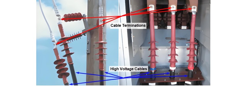
عواملی که باید در پایانیابی ماشینهای الکتریکی و انتقال کابلهای زیرزمینی به روی زمین در نظر گرفته شود
عوامل در پایانیابی ماشینهای الکتریکی
در زمان پایانیابی ماشینهای الکتریکی، مجموعه جامعی از عوامل باید به دقت در نظر گرفته شود تا عملکرد ایمن، قابل اعتماد و کارآمد تضمین شود:
باربر و ساختارهای پشتیبان: طراحی، مواد و قدرت باربرها و ساختارهای پشتیبان آنها حیاتی است. آنها باید بتوانند جریانهای الکتریکی، تنشهای مکانیکی و نیروهای ممکن از مدار کوتاه را تحمل کنند و همزمان تراز و ثبات مناسب را حفظ کنند.
ساختار عایقبندی قطعکننده مدار: تمامیت عایقبندی در قطعکنندههای مدار برای جلوگیری از شکست الکتریکی حیاتی است. آن باید بتواند ولتاژ اسمی، ولتاژهای موقتی فراتر از حد و شرایط محیطی را بدون خرابی تحمل کند.
تحلیل رهگذری جزئی (PD): انجام تحلیل رهگذری جزئی به تشخیص علائم اولیه تخریب عایقبندی کمک میکند. رهگذریهای جزئی میتوانند ضعفهای ممکن در سیستم عایقبندی را نشان دهند که اگر بدون رسیدگی باقی بمانند، میتوانند منجر به خرابیهای ویرانگر شوند.
مواد عایقبندی: انتخاب ماده عایقبندی، چه نفت، گاز شش فلوئورید سولفور (SF6) یا خلاء باشد، تأثیر قابل توجهی بر عملکرد دارد. هر ماده مزایا و محدودیتهای خاص خود را در زمینه قدرت عایقبندی، توانایی خاموش کردن قوس الکتریکی، تأثیر محیطی و نیازهای نگهداری دارد.
حالت سیستم ضربهای: سیستم ضربهای که مولفهها را در محل ثابت میکند باید در وضعیت خوبی باشد. سیستم ضربهای معیوب میتواند منجر به اتصالات آزاد، مقاومت الکتریکی افزایش یافته و گرم شدن ممکن شود.
نوع گاز خنککننده: برای ماشینهایی که به سیستمهای خنککننده گازی متکی هستند، نوع گاز خنککننده تأثیر قابل توجهی بر تشعشع حرارت و عملکرد کلی دارد. گازهای مختلف رسانایی حرارتی و ظرفیت حمل حرارت متفاوتی دارند.
نزدیکی مولفههای زمینشده به هادیهای ولتاژ بالا: مکان مولفههای زمینشده نسبت به هادیهای ولتاژ بالا بسیار مهم است. نزدیکی زیاد میتواند خطر نشت الکتریکی، افشانه یا تداخل را افزایش دهد که نیازمند عایقبندی و فاصلهگذاری صحیح است.
پایانیابی برای انتقال کابلهای زیرزمینی به خطوط هوایی
پایانیابیهای انتقال کابلهای زیرزمینی به خطوط هوایی، که به طور معمول OH/OG نامیده میشوند، نقش مهمی در شبکههای توزیع الکتریکی ایفا میکنند. این پایانیابیها معمولاً برای سیستمهای با ولتاژ اسمی تا ۳۶ کیلوولت طراحی شدهاند. وظایف اصلی آنها شامل اتصال سیستم توزیع به تجهیزات نقل و انتقال برق داخل ساختمان یا خارج ساختمان و تسهیل مسیریابی توان الکتریکی بدون نیاز به عبور خطوط هوایی از مناطق شهری است.
پایانیابیهای OH/OG با کابلهای عایقبندی شده با نفت-کاغذ و پلیاتیلن متقاطع (XLPE) سازگار هستند که میتوانند یکهستهای یا سههستهای باشند. آنها در خارج از ساختمان نصب میشوند و روی ساختارهای فلزی که به سختی به ستونهای خطوط هوایی از جنس چوب، بتن یا فلز متصل شدهاند، نصب میشوند، همانطور که در شکل ۱ نشان داده شده است.
یکی از الزامات ایمنی اساسی برای پایانیابیهای OH/OG این است که ساختارهای فلزی آنها باید به درستی زمین شوند. این زمینکشی برای محافظت در برابر شوکهای الکتریکی، تشعشع جریانهای خطا و تضمین ایمنی کلی سیستم الکتریکی لازم است.
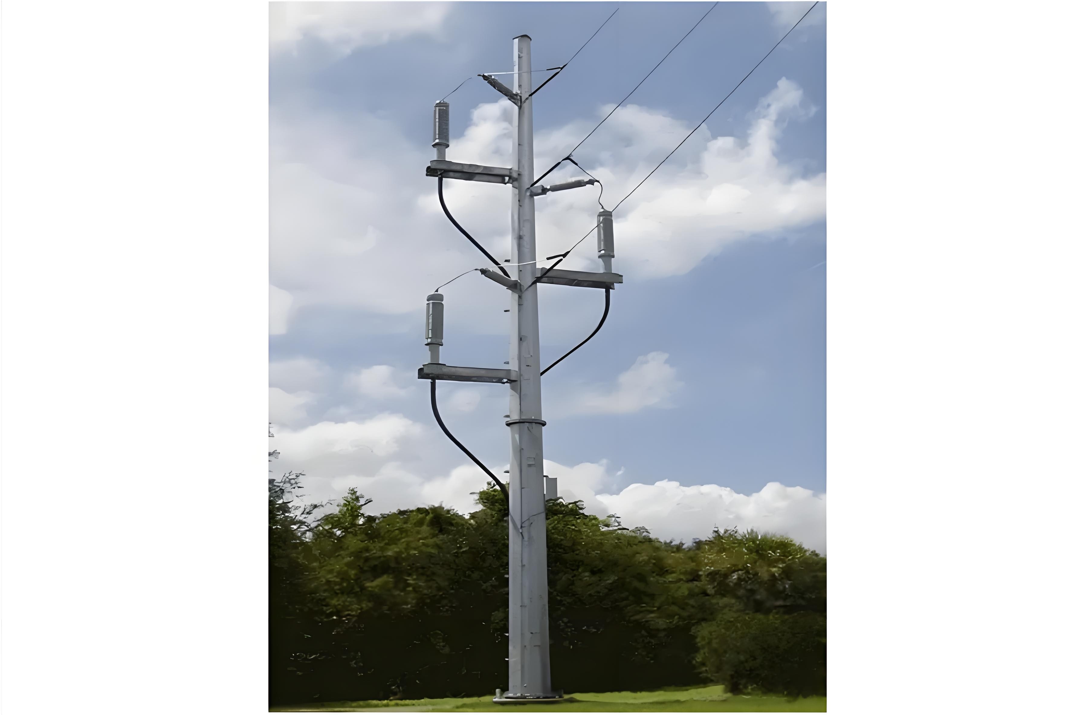
الزامات برای ساختارهای فلزی OH/OG و نصب کابلها، و پایانیابیهای زاویهدار
الزامات ساختارهای فلزی OH/OG و نصب کابلها
ارتفاع ساختار فلزی OH/OG (هوایی/زیرزمینی) دلخواه نیست؛ بلکه باید به صورت строгий виконуватися мінімальна дистанція ізоляції до землі, визначена відповідними промисловими стандартами. Це виконання є важливим для забезпечення безпеки людей, обладнання та загальної електричної системи, запобігання електричних аварій, таких як неправильний контакт або струмові пробої до землі.
При встановленні кабелів для пайєнтації OH/OG, їх слід розташовувати на стороні стовпа, яка спрямована від наїжджого руху. Це розташування мінімізує ризик пошкодження від автомобілів, таким чином підвищуючи надійність та тривалість електричної інфраструктури. Окрім того, протягом процесу встановлення та після того, як кабелі займають своє остаточне положення, необхідно, щоб вони не були зігнуті за межами мінімального внутрішнього радіусу згину, вказаного виробником. Невідповідність цьому вимоги може призвести до внутрішнього пошкодження ізоляції та провідників кабелю, що потенційно може призвести до електричних аварій. В деяких випадках, для забезпечення мінімального радіусу згину, можуть бути необхідні вищі стовпи, що додає додаткове розгляд у фазах планування та встановлення. Крім того, пайєнтації OH/OG повинні бути спроектовані з заходами захисту від тварин. Це захищає кабелі від пошкоджень, спричинених тваринами, що в іншому випадку може призвести до відключень електроенергії та ризиків безпеки.
Завершення ліктів
Завершення кабелів часто використовуються для підключення кабелів до терміналів різного обладнання, включаючи трансформатори, двигуни та передзамовлені вузли перетворення. Однак, через специфічні умови електричного встановлення або характер терміналів обладнання, є випадки, коли підключення кабелю до втулок потребує герметизації. У таких ситуаціях, завершення ліктів, як показано на малюнку 2, є вибором за вибором. Ці спеціалізовані завершення не лише забезпечують надійне електричне підключення, але й надають необхідну функцію герметизації, захищаючи електричну систему від неблагополучних факторів середовища та забезпечуючи її стабільну роботу.
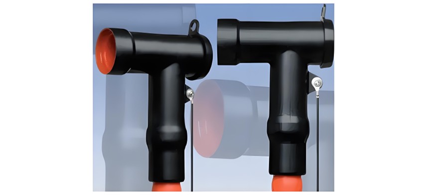
Завершення ліктів та їх застосування в блоках основного кільця (RMU)
Завершення ліктів мають ключове та спеціалізоване призначення, особливо коли йдеться про підключення кабелів до втулок блоків основного кільця (RMU). RMU - це компактні, самостійні, повністю ізольовані вузли перетворення, які типово використовують гексафторид сульфуру (SF6) як ізоляційний серед. Широко використовуються в вторинних мережах розподілу, ці одиниці відіграють ключова роль у управлінні та розподілі електричної енергії на місцевому рівні.
Однією з ключових характеристик RMU є їх конструкція для витримування внутрішніх дуг, що підвищує безпеку та надійність електричної системи. Живі частини RMU розроблені так, щоб бути безпідтримковими, що зменшує потребу в частих втручаннях та мінімізує простої. Крім того, їх модульна природа дозволяє легко розширювати систему на місці встановлення, дозволяючи системі адаптуватися до зміни потреб у енергії з часом.
Функції комутації та захисту в RMU виконуються за допомогою комутаторів-відокремлювачів в поєднанні з предохранителями або автоматичними вимикачами. Ця конфігурація забезпечує безпечне відокремлення електричної системи, швидке виявлення та усунення аварій, а також підтримку цілісності мережі розподілу.
Завершення ліктів не лише корисні для підключення кабелів до втулок RMU, але також знаходять застосування, коли потрібно під'єднати кілька кабелів до однієї втулки електричного обладнання. Як показано на малюнку 3, ці завершення надають практичне та надійне рішення для таких складних підключень кабелів до обладнання, сприяючи ефективному розподілу електричної енергії, підтримуючи цілісність та безпеку загальної системи.
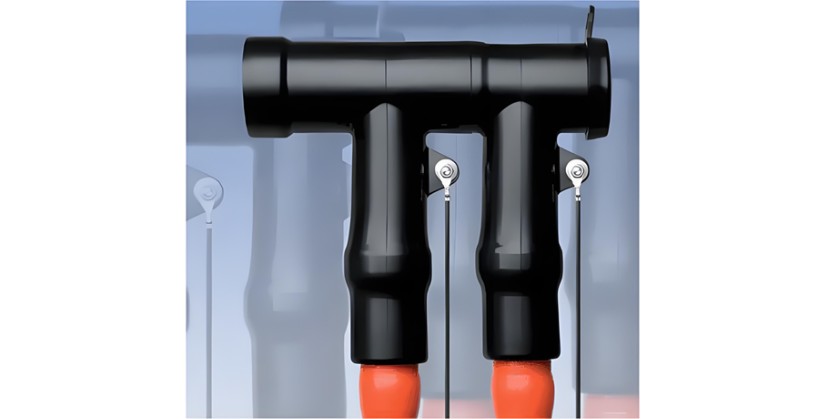
Elastimold Cable Joints & Terminations
Elastimold is a well - known brand that offers a comprehensive range of equipment and accessories for cable splicing and termination, designed for rated voltages of up to 36 kV.
Elastimold cable terminations come in both single - piece and modular designs. These versatile models are suitable for various applications, including the transition from underground cables to bare overhead conductors, connections to live - front equipment, and elbow connections, making them adaptable for both indoor and outdoor use. They can be seamlessly integrated into oil, SF6, and air - insulated high - voltage switchgear, as well as transformers, motors, and capacitors.
The designs of Elastimold products incorporate advanced silicone rubber insulating materials. These materials provide essential resistance against creep, electrical strikes, weathering, and contamination, ensuring reliable performance even in the harshest conditions. The compact and lightweight nature of Elastimold units allows for easy installation in confined spaces and enables free - hanging applications.
Elastimold devices are also ATEX - certified. ATEX, derived from the French title of the 94/9/EC (European Commission) directive "Appareils destinés à être utilisés en ATmosphères Explosibles" (Equipment to be installed in explosive atmospheres), these high - voltage bushings are suitable for use within oil or air - insulated switchgear and transformers in hazardous areas, such as those found in the oil, gas, and petrochemical industries. The manufacturing of Elastimold equipment adheres to international standards set by IEC (International Electrotechnical Commission), ANSI/IEEE (American National Standards Institute/Institute of Electrical and Electronics Engineers), and CENELEC (European Committee for Electrotechnical Standardization).
Elastimold offers several specialized devices for specific applications:
Separable Elbow Connectors and Accessories: These are load - break connectors that provide a convenient means of connecting and disconnecting cables and equipment in power distribution systems. Load - break elbows are designed for energized operation using standard hot - stick tools, enabling load make/break operations and providing a visible disconnect. The components can be isolated using insulated caps, plugs, and parking bushings.
Metal Oxide Varistor (MOV) Surge Arresters: These arresters are fully shielded and fully - submersible, designed for overvoltage protection. They feature 200 A separable connector interfaces for easy attachment to other Elastimold accessories. Elastimold arresters offer high - voltage protection against lightning and switching surges for transformers, cables, equipment, and other components typically found in underground power distribution systems. Proper placement, voltage selection, and coordination with riser pole arresters can significantly enhance protective margins and minimize damaging surge voltages. Typical applications include installing arresters at the end of a radial system or at both ends of an open point on a loop system, with additional arresters added at strategic upstream locations for optimal protection.
Fused Elbows: These combine replaceable current - limiting fuses for current protection in OH/OG cable terminations with 200 A separable connector interfaces for compatibility with other Elastimold accessories.
Raychem is another commonly recognized brand in the field of cable splicing and termination equipment.
Terminations for GIS (Gas Insulated Substations)
When the available space for substation installation is limited or environmental conditions are extremely harsh, a Gas Insulated Substation (GIS) is often the preferred solution. GIS is a compact, multi - component assembly housed within a grounded metallic enclosure. It contains bus bars, circuit breakers, isolators, and instrument transformers, with compressed sulfur hexafluoride (SF6) gas serving as the primary insulation medium, ensuring reliable phase - to - ground insulation. While GIS are typically installed indoors, outdoor models are also available.
GIS units are equipped with cable termination enclosures where cable terminations are installed. According to IEC Standard 60859, both the enclosures and cable terminations must meet specific dimension requirements to ensure interchangeability. Cable terminations for GIS are suitable for gas, oil - paper, and XLPE - insulated cables and share many components with the cable joints previously discussed.
Features of GIS Cable Terminations
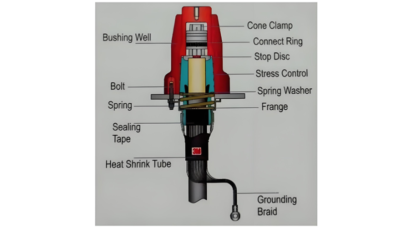
The main features of GIS cable terminations include:
Cable Lug: Facilitates the connection between the cable conductor and the termination.
Box Body: Typically made of aluminium alloy or a similar material, providing structural support and protection.
Reliable Support Insulator: High - grade, non - tracking epoxy insulators offer excellent mechanical and electrical properties. These insulators are compatible with SF6 gas by - products, ensuring a long service life for the termination. Their design also allows for an optional cable shield break.
Filling Compound: Such as transformer oil, polybutene oil, or similar substances, which help in insulation and stress relief.
Stress Control Cone with Bundle Tape: Manages electrical stress at the cable insulation - termination interface.
Rigid Cable Support: The connector is securely locked in place by a threaded hood at the top of the support insulator. This design ensures that the electrical connection between the GIS and the termination is not subjected to mechanical forces from the cable.
Positive Sealing System: A double "O" ring sealing system is employed to seal the termination oil compartment from the GIS SF6 compartment. Fully retained gaskets are compressed to prevent the ingress of atmospheric elements into the termination interior.
Earthing Clamp: Provides a secure connection for earthing purposes.
Figure 4 illustrates a schematic of a GIS cable termination. Some models available on the market do not require the use of oil, eliminating the need for an oil housing.
Sealing, Connection, and Installation Requirements for GIS Cable Terminations
Sealing System
The sealing system of GIS cable terminations is of paramount importance and must be meticulously designed. Its primary function is to prevent the leakage of oil or gas into the GIS. A compromised seal could lead to insulation failures, gas loss, and potential safety hazards. By ensuring a robust and reliable sealing mechanism, the integrity of the GIS environment and the overall electrical system is maintained.
Mating Connection Piece
The GIS supplier is responsible for providing a mating connection piece that is specifically designed to be fitted to the cable end. This component is crucial for establishing a secure and electrical connection between the cable and the GIS. The precise design and compatibility of the mating connection piece are essential to ensure seamless integration and optimal performance of the cable - GIS interface.
Isolation and Testing Facilities
To guarantee the safety and reliability of the electrical system, proper facilities must be provided to safely isolate a feeder cable. This isolation capability is necessary during maintenance, repairs, or fault - finding operations. Additionally, provisions should be made to connect a high - voltage test cable to either the GIS or the cable itself. These testing facilities enable routine inspections and diagnostic tests to assess the condition of the cable and the GIS, helping to identify potential issues before they escalate into major problems.
Required Tools and Accessories for GIS Termination Installation
For the successful installation of GIS cable terminations, a specific set of proper tools and accessories is indispensable:
Panduit Pliers: These pliers are specifically designed for installing bundle tape around the stress cone. The accurate application of the bundle tape is crucial for managing electrical stress and ensuring the long - term reliability of the termination.
Circlip Pliers: Used for the installation of the top fitting, circlip pliers provide the necessary grip and precision to secure this important component in place.
Adapter Flange: The adapter flange plays a key role in facilitating the connection between different components, ensuring a proper fit and alignment within the GIS termination system.
Top Fitting Removal Kit: This kit is essential for maintenance and repair operations, allowing for the safe and efficient removal of the top fitting when required.
Re - assembly Kit: The re - assembly kit contains all the necessary components and hardware to put the termination back together after maintenance or repairs, ensuring that all parts are replaced correctly.
Earthing Kit: An earthing kit is vital for establishing a secure electrical connection to the ground, which is essential for the safety of the electrical system and personnel.
Screen Connection: The screen connection ensures the proper grounding and shielding of the cable, reducing electromagnetic interference and enhancing the overall performance of the cable - GIS system.


