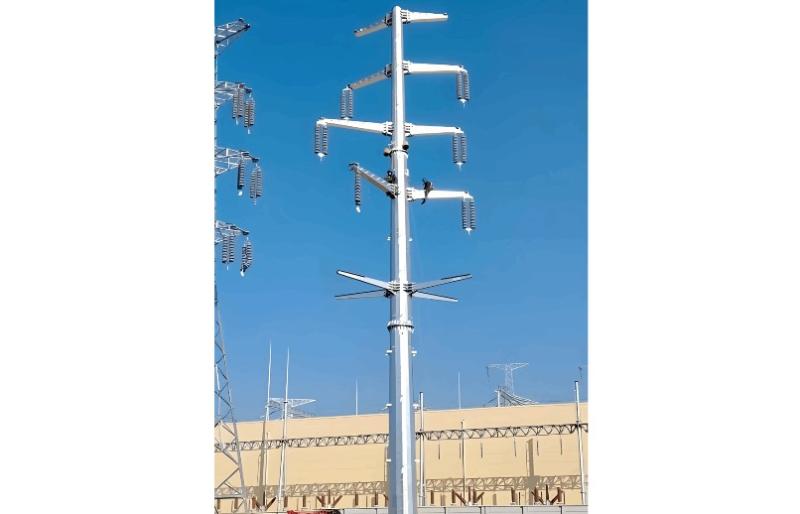
Besides ultra-high voltage AC substations, what we encounter more frequently are power transmission and distribution lines. Tall towers carry conductors that leap across mountains and seas, stretching into the distance before reaching cities and villages. This is also an interesting topic—today, let's explore transmission lines and their supporting towers.
Power Transmission and Distribution
First, let’s understand how electricity is delivered. The electric power industry primarily consists of four stages: power generation, transmission, (substation) distribution, and consumption.
Generation includes various types of power generators—traditional ones such as coal-fired and hydroelectric power plants, as well as modern sources like wind and solar energy. All of these fall under the generation category.
Transmission relies on transmission lines and towers.
Substation (or Transformation) mainly uses transformers. Step-up transformers at power plants increase voltage for efficient long-distance transmission, while step-down transformers on the distribution side reduce voltage to levels suitable for regional distribution networks and end users.
Distribution on the consumer side involves various step-down transformers, as well as medium- and low-voltage equipment, switchgear, and wiring.
Consumption refers to electrical devices in homes, as well as power usage in municipal infrastructure, buildings, industrial facilities, and other applications.
In terms of structure, transmission lines are divided into two main types: overhead transmission lines and cable lines. Below is a schematic diagram of a power transmission system:

What voltage levels are suitable for long-distance power transmission? To reduce transmission losses and improve efficiency, AC voltages of 500 kV and above are typically used for power transmission. Voltages in the range of 500 kV to 750 kV are classified as Extra High Voltage (EHV) AC transmission, while 1000 kV AC systems are known as Ultra High Voltage (UHV) AC transmission. In contrast, lines operating from medium voltage up to 110 kV–330 kV are generally categorized as distribution lines. Note that these classifications may vary with increasing power demand, system capacity, and regional energy distribution patterns.
Voltage levels refer to line-to-line voltage—that is, the voltage between any two of the three phases (A, B, and C). The 220 volts used in households is the phase voltage, which is the voltage between any one phase and ground. In reality, residential power supply originates from a 380-volt line voltage system. Only at the building entrance are the three phases (A, B, and C) separated—each phase may feed a different unit of a residential building. What you commonly see in cities or residential communities is a square, box-like structure—this is a pad-mounted (or box-type) substation (as shown in the figure below).

The box-type substation integrates medium-voltage equipment, transformers, and low-voltage distribution devices. It transforms the urban medium-voltage distribution network (typically 10 kV or 20 kV) into 380 V power suitable for residential or municipal use. You may not see the wiring, as urban distribution networks in China today mostly use underground cables. However, in some older residential areas or rural regions, you can still observe overhead lines connecting transformers and then running to buildings or individual consumers.
In open areas, the overhead transmission lines we commonly see consist of towers and conductors. There are various tower types, and transmission lines are categorized as either direct current (DC) or alternating current (AC).
China’s power generation and consumption exhibit significant geographical imbalance. Abundant energy resources such as coal, wind, solar, and hydropower are concentrated in the vast western regions, while major load centers lie thousands of kilometers away in the central and eastern regions. This geographical mismatch makes long-distance power transmission an essential solution.
In recent years, with the rapid development of large-scale wind and solar power bases, the demand for long-distance power transmission has continued to grow. As the backbone of power delivery, the construction of ultra-high-voltage (UHV) grids has accelerated, providing strong momentum for China’s energy transition and sustainable development. All of these long-distance transmission systems rely on transmission towers and overhead lines to interconnect the grid.
Overhead Transmission Lines
An overhead transmission line consists of conductors suspended from towers using insulators and hardware, ensuring safe clearance between the conductors and the ground or buildings. The primary function of a transmission line is to deliver electrical energy, connect power plants and substations, enable parallel operation, and integrate the power system into a unified network.
Overhead lines offer advantages such as lower investment costs, faster construction, simple and convenient installation, easy identification of faults and potential hazards, and straightforward maintenance and repair. For long-distance transmission, overhead lines are predominantly used due to their high power capacity. The longer the transmission distance, the higher the required voltage level.
However, because overhead lines are widely distributed and operate continuously in outdoor environments, they are frequently affected by surrounding conditions and natural factors. This leads to various operational faults, including lightning strikes, wind damage, ice accumulation, pollution flashover, external interference, conductor galloping, and bird-related incidents.
Moreover, when working with high-voltage switchgear, engineers commonly deal with high-voltage (HV), extra-high-voltage (EHV), and ultra-high-voltage (UHV) systems, most of which are interconnected via overhead lines. Consequently, technical requirements for high-voltage equipment are closely tied to line conditions—such as operating environment and service conditions. Understanding the characteristics and fault behaviors of overhead lines is therefore essential for comprehending the technical specifications of high-voltage equipment.
Components of Overhead Transmission Lines
The main components of an overhead transmission line include foundations, towers, conductors, insulators, hardware (fittings), lightning protection devices (such as overhead ground wires and surge arresters), and grounding systems. Modern lines may also include auxiliary components like optical ground wire (OPGW) and power line carrier communication systems.
(1) Conductors
Conductors transmit current and deliver electrical energy. Single-conductor per phase is typical for standard lines. However, for EHV and high-capacity transmission lines, bundled conductors—using two, three, four, or more sub-conductors (often arranged in a circular configuration)—are commonly adopted. This reduces corona discharge, minimizes power loss, and decreases interference with radio, television, and other communication signals.
(2) Shield (Ground) Wires and Grounding Systems
Shield wires are suspended at the top of transmission towers and connected to the grounding system at each tower via down conductors. During a lightning strike, the shield wire—positioned above the phase conductors—intercepts the lightning, safely diverting the current through the grounding system into the earth. This reduces the probability of direct strikes to the conductors, protects line insulation from overvoltage damage, and ensures reliable operation. Shield wires are typically installed along the entire length of lines rated 110 kV and above and are commonly made of galvanized steel strands.
(3) Towers (Pylons)
Towers support the conductors and shield wires along with associated hardware, maintaining safe electrical clearances between conductors, towers, the ground, and any cross-over structures or buildings.
(4) Insulators and Insulator Strings
Insulators are the key insulation components of a transmission line. They support or suspend the conductors while electrically isolating them from the towers, ensuring reliable dielectric strength. Subjected to mechanical stress, electrical voltage, and corrosive atmospheric gases, insulators must possess sufficient mechanical strength, insulation performance, and resistance to degradation.
(5) Hardware (Fittings)
Transmission line hardware plays a critical role in supporting, securing, connecting, and protecting conductors and ground wires, ensuring robust and reliable connections. Hardware is classified into five main types based on function: line clamps, connector fittings, splice fittings, protective fittings, and guy wire fittings.
(6) Foundations
The foundation anchors the tower to the ground, preventing tilting, collapse, or subsidence.
We will examine each of these components in detail in subsequent discussions.
(7) Towers (Pylons)
There are numerous types of transmission lines and towers, with voltage levels reaching up to 1000 kV. Tower materials include wood, concrete, steel lattice, and steel tube structures, and their shapes and designs vary widely. The purpose of a transmission line is to deliver electrical power from one end to the other with minimal losses. Therefore, within the same voltage class, lines are designed to minimize impedance and maximize conductor cross-sectional area. Towers serve to support the lines and prevent contact with other conductive objects that could cause grounding faults. As such, they are built to be tall and structurally stable. The image below shows common tower types.

Based on their actual functions in engineering applications, towers are further classified into several types: straight-line (suspension) towers, angle (corner) towers (used for changing direction), terminal towers (for connecting to and from substations), transposition towers (used for phase rotation), and large-span towers (designed to cross major rivers, lakes, or straits). At the base of each tower is the foundation. The conductors are suspended from cross-arms via insulator strings.
If you look closely at a steel lattice tower, you’ll notice two small "horns" extending upward—one on each side—carrying thin wires. These are not for power transmission; they are overhead ground wires (shield wires), also known as earth wires, used for lightning protection.
Transmission towers come in various shapes. For single-circuit lines, common configurations include the "wine-glass" type with horizontally arranged conductors and the "cat-head" type with triangular conductor arrangement. In areas with limited right-of-way or in economically developed regions where land is scarce, compact towers carrying two or even four circuits on the same structure are often used. For ultra-high-voltage (UHV) DC transmission lines, there are also T-type towers, which support two circuits hanging beneath—on one side the positive pole, and on the other side the negative pole.

A transmission line corridor refers to the strip-shaped area extending laterally from the outermost conductors of a high-voltage overhead power line. Its width is determined by the voltage level and regulated under the Regulations on the Protection of Electric Power Facilities. For example, the protected zone for a 500 kV line is 20 meters wide. While limited agricultural activities are permitted within this zone, stacking flammable materials or constructing buildings is strictly prohibited.
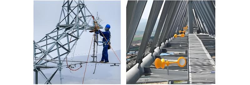
You may have also noticed numerous spike-like devices and small "windmills" installed on transmission towers. What are these for? They are all bird deterrents! The anti-bird spikes prevent birds from building nests, while the small spinning "windmill" devices scare birds away—both are commonly mounted on towers.
The structure of transmission towers provides an ideal location for birds to build nests. However, bird droppings are conductive. When excreted onto insulator strings, they can create a conductive path between the conductor and ground, potentially causing flashover, ground faults, or even phase-to-phase short circuits. Therefore, power lines are highly vulnerable to what might be called “angry birds.” In addition, tall trees near transmission lines (or corridors) can also threaten safe operation—for instance, by causing ground clearance violations or short circuits—and must therefore be regularly trimmed.


