Reactor (Inductor): Pêşkêş û Tîpên
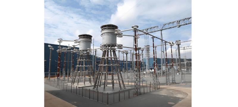
Reactor, ya heta inductor, wêjêna mehniyayê di derbarê de daxistin da ku ampera lew gerîn. Buna, her gerînî ku ampera li ser we têne, tevahî lîndansîya hewce. Lekin, lîndansîya gerînê bêdikî ye û wêjêna mehniyayê ya biyêbîn daxistin da. Reactorên pratîkî bi girandina gerînê bi şêkili solenoid, ya heta reactor ên core-air, in. Ji bo zêdekirina lîndansî, core-ê ferromagnetic di solenoida de hatîn girtin, u formê reactor ên core-ferro hatîn.
1. Shunt Reactor
Prototype ya shunt reactors ji bo testkirina full-load ya generatoran ve hatîn bikar anîn. Shunt reactors ên core-ferro guhertinên magneticên alternatif yên di navbera navberên core-ê de daxistin, ku nivîsên sazî yên 10 dB yê werger û transformerên berbasdarên berbasdar hatine. Shunt reactors ampera AC (alternating current) han û ji bo kompensasyonê systemê reaktance capacitance hatîn bikar anîn. Her du hemî bi thyristors hatîn pêşankirin ji bo rêgulasyonê pêşdebir û continuous reaktive ampera.
2. Series Reactor
Series reactors ampera AC han û bi capacitorên power hatîn pêşankirin bi series resonance circuit ji bo harmonics steady-state (mînace, 5th, 7th, 11th, 13th harmonics). Series reactors typîkî yên impedance values 5–6% ne û high-inductance types hatîn hesab kirin.
3. Tuning Reactor
Tuning reactors ampera AC han û bi capacitorên pêşankirin bi series resonance ji bo harmonic frequency (n) specifik, u kêmûnê ya wan harmonic component. Common tuning orders n = 5, 7, 11, 13, û 19 ne.
4. Output Reactor
Output reactor kapasitive charging ampera di cable motoran de kêmûn dikin û rate of voltage rise across motor windings ji 540 V/μs ve piştgirî dikin. Divê bi mafey cable yên di var drive-a variable frequency (VFD) (4–90 kW) û motorê de piştguh kirin ji 50 metr. Output voltage (reducing switching edge steepness) VFD hatine kêfîn û disturbances û stress inverter components such as IGBTs hatine kêmûn kirin.
Application Notes for Output Reactors:
To extend the distance between VFD and motor, use thicker cables with enhanced insulation, preferably non-shielded types.
Features of Output Reactors:
Suitable for reactive power compensation and harmonic mitigation;
Compensates for distributed capacitance in long cables and suppresses output harmonic currents;
Effectively protects VFDs, improves power factor, blocks grid-side interference, and reduces harmonic pollution from rectifier units to the grid.

5. Input Reactor
Input reactor voltage drops on the grid side during converter commutation kêmûn dikin, harmonics kêmûn dikin, û parallel converter groups decouples. Voltage transients or switching operations di ser gridê de current surges piştgirî dikin. Ji bo grid short-circuit capacity to VFD capacity ratio exceeds 33:1, relative voltage drop of the input reactor for single-quadrant operation 2% û for four-quadrant operation 4% dibînin. Grid short-circuit voltage exceeds 6% reactor may operate. For a 12-pulse rectifier unit, line-side input reactor with at least 2% voltage drop required. Input reactors widely used in industrial and factory automation control systems. Installed between the power grid and VFDs or speed regulators, they surge voltages and currents generated by these devices kêmûn dikin, significantly attenuating higher-order and distorted harmonics in the system.
Features of Input Reactors:
Suitable for reactive power compensation and harmonic filtering;
Limits current surges caused by grid voltage transients and switching overvoltages; filters harmonics to reduce voltage waveform distortion;
Smoothes voltage spikes and rectifier commutation notches in bridge circuits.
6. Current-Limiting Reactor
Current-limiting reactors typically used in distribution circuits. They are connected in series with feeder lines branching from the same busbar to limit short-circuit current and maintain bus voltage stability during faults, preventing excessive voltage drops.
7. Arc Suppression Coil (Petersen Coil)
Widely used in resonant grounded systems at 10kV–63kV, arc suppression coils are increasingly of dry-type cast resin design due to the trend toward oil-free substations, especially for systems below 35kV.
8. Damping Reactor (often synonymous with Series Reactor)
Connected in series with capacitor banks or compact capacitors, damping reactors limit inrush current during capacitor switching—similar in function to current-limiting reactors. Filter Reactor: When connected in series with filter capacitors, they form resonant filter circuits, typically used for 3rd to 17th harmonic filtering or higher-order high-pass filtering. HVDC converter stations, phase-controlled static VAR compensators, large rectifiers, electrified railways, and high-power thyristor-based electronic circuits are all harmonic current sources that must be filtered to prevent harmonic injection into the grid. Power utilities have specific regulations regarding harmonic levels in power systems.
9. Smoothing Reactor (DC Link Reactor)
Smoothing reactors used in DC circuits after rectification. Since rectifier circuits produce a finite number of pulses, the output DC voltage contains ripple, which is often harmful and must be suppressed by a smoothing reactor. HVDC converter stations equipped with smoothing reactors to make the output DC as close to ideal as possible. Smoothing reactors also essential in thyristor-controlled DC drives. In rectifier circuits, especially medium-frequency power supplies, their main functions include:
Limiting short-circuit current (during inverter thyristor commutation, simultaneous conduction is equivalent to a direct short-circuit at the rectifier bridge output); without a reactor, this would cause a direct short;
Suppressing the influence of medium-frequency components on the utility power grid;
Filtering effect—rectified current contains AC components; high-frequency AC is impeded by the large inductance—ensuring continuous output current waveform. Discontinuous current (with zero-current intervals) would cause the inverter bridge to stop, resulting in an open-circuit condition at the rectifier bridge;
In parallel inverter circuits, reactive power is exchanged at the input; therefore, energy storage elements—reactors—are essential in the input circuit.
Important Notes
Reactors in power grids used to absorb capacitive reactive power generated by cable lines. By adjusting the number of shunt reactors, system operating voltage can be regulated. Ultra-high voltage (UHV) shunt reactors serve multiple functions related to reactive power management in power systems, including:
Mitigating the capacitive effect on lightly loaded or no-load transmission lines, reducing power-frequency transient overvoltages;
Improving voltage distribution along long transmission lines;
Balancing reactive power locally under light load conditions, preventing unreasonable reactive power flow and reducing line power losses;
Reducing steady-state power-frequency voltage on high-voltage busbars when large generators are synchronized to the grid, facilitating generator synchronization;
Preventing self-excitation resonance that may occur when generators are connected to long transmission lines;
When the reactor neutral is grounded via a small reactor, the small reactor can compensate for inter-phase and phase-to-ground capacitance, accelerating the self-extinction of residual currents and enabling single-pole auto-reclosing.
Reactors connected either in series or in parallel. Series reactors typically used for current limiting, while shunt reactors commonly used for reactive power compensation.
Shunt Reactor: In ultra-high voltage long-distance transmission systems, they are connected to the tertiary winding of transformers to compensate for the capacitive charging current of transmission lines, limit voltage rise and switching overvoltages, and ensure reliable system operation.
Series Reactor: Installed in capacitor circuits, they are used when the capacitor bank is energized.


