I. Ինչ է ցանցի լարման գերլարումը:
Ցանցի լարման գերլարումը հղում է էլեկտրաէներգետիկ համակարգերում կամ շղթաներում, որտեղ լարումը գերազանցում է նորմալ աշխատանքային տիրույթը:
Ընդհանուր առմամբ, էլեկտրաէներգետիկ հաճախության դեպքում, եթե փոփոխական հոսանքի լարման կարդացումը (RMS) բարձրանում է առաջնորդյալ արժեքից ավելի քան 10% և շարունակվում է ավելի քան 1 րոպե, այն կարող է համարվել ցանցի լարման գերլարում:
Օրինակ, Չինաստանում ընդունված 380V եռաֆազ ցանցի համակարգում, եթե լարումը գերազանցում է 418V և շարունակվում է որոշ պարագայում, կարող է ակտիվացնել ցանցի լարման գերլարում:
Ֆոտովոլտային (PV) կայանակներում ցանցի լարման իրականացնող ինվերտերը պատասխանատու են ցանցի լարման իրականաց մոնիտորինգի համար:
Ինվերտերը ընդհանուր առմամբ 装备了高精度电压传感器来收集实时电网电压信号。这些传感器将收集到的电压信号传输给逆变器的控制系统,系统分析和处理这些信号以确定电网电压是否在规定范围内。
一旦检测到电网电压超过预设的安全范围,逆变器将立即激活保护机制,关闭并从电网断开,以防止过电压损坏设备,并确保设备和操作人员的安全。
此外,在一些大型光伏电站中,还安装了专门的电能质量监测装置,对各种电网参数进行全面、实时的监测,以便及时发现和处理诸如电压过压等电能质量问题。
II. Voltage Overvoltage Faults ի պատճառները
(1) Գծի արդյունքները. Կաբելի իմպեդանսի ազդեցությունը
Ինվերտերի և ցանցի միացման կետի միջև գտնվող կաբելները կարևոր դեր են խաղում էլեկտրաէներգիայի փոխանցման գործում:
Եթե կաբելը չափազանց բարակ է, նրա դիմադրությունը ավելանում է: Օհմի օրենքի (U = I×R) համաձայն, հաստատուն հոսանքի դեպքում ավելի բարձր դիմադրությունը առաջացնում է ավելի բարձր լարման կորուստ, որը իր հերթին բարձրացնում է ինվերտերի կողմից արտածվող փոփոխական հոսանքի լարումը:

Միացման կետից հեռու գտնվող կաբելները նույնպես ավելացնում են դիմադրությունը, որը կարող է առաջացնել նման լարման բարձրացում: Օրինակ, հեռավոր տարածաշրջաններում գտնվող ֆոտովոլտային կայանակներում, որտեղ ցանցի միացման կետը հեռու է, անհամապատասխան սպեցիֆիկացիայով կաբելների օգտագործումը կարող է հեշտությամբ առաջացնել լարման գերլարում կաբելի իմպեդանսի արդյունքում:
Եթե կաբելները փոխադարձ համակցված են, նրանց ինդուկտիվությունը ավելանում է: Այսպիսով, փոփոխական հոսանքի շղթաներում ինդուկտիվությունը արգելափոխ է հոսանքի հոսքը, ավելի շատ խառնում է լարման բաշխումը և կարող է ակտիվացնել լարման գերլարում:
Սխալ գծային միացում
Ֆոտովոլտային կայանակի սկզբնական տեղադրման ժամանակ սխալ այլընտրանքային հոսանքի կաբելների միացումը (օրինակ, անջատ կետի միացումը հոսանքի կետին) կարող է առաջացնել անսովոր լարում: Այսպիսով, ինվերտերը կարող են գրանցել լարում, որը չի համապատասխանում իրական ցանցի լարմանը, որը կարող է ակտիվացնել գերլարման պաշտպանական մե커անիզմը:
Ինվերտերի աշխատանքի ընթացքում ցանցի կողմից միացված կաբելների անառաջ կամ անհաստատուն միացումը կարող է ավելացնել կոնտակտի դիմադրությունը: Ջուլի օրենքի (Q = I²Rt, որտեղ Q-ն ջերմությունն է, I-ն հոսանքը, R-ն դիմադրությունը, t-ն ժամանակը) համաձայն, ավելի բարձր կոնտակտի դիմադրությունը առաջացնում է ավելի շատ ջերմություն, որը առաջացնում է լոկալ ջերմաստիճանի բարձրացում: Այս պայմանները վերաբերում են գծի էլեկտրական հատկությունների կրկնակի վերացմանը, ինվերտերի կողմից կարող է առաջացնել կետային լարման բարձրացում և ակտիվացնել լարման գերլարում:
(2) Ցանցի կառուցվածքը և բեռնային արդյունքները. Ցանցի տարողության և բեռնային արդարացման հակասությունը
Որոշ տարածաշրջաններում, հատկապես հեռավոր գյուղային տարածաշրջաններում կամ ցանցի ինֆրակառուցվածքի հետադարձ զարգացած տարածաշրջաններում, ցանցի բեռնային արդարացման տարողությունը սահմանափակ է: Եթե նույն էլեկտրաէներգետիկ տարածաշրջանում տեղադրված ֆոտովոլտային տեղադրումների տարածքը չափազանց մեծ է, շատ ֆոտովոլտային էլեկտրաէներգիա կանցնում է ցանցի միջոցով: Եթե ցանցը չի կարող անմիջապես և արդյունավետորեն այդ էլեկտրաէներգիան արդարացնել, ցանցի լարումը կարող է բարձրանալ:
Տրանսֆորմատորների առաջացրած հարցերը
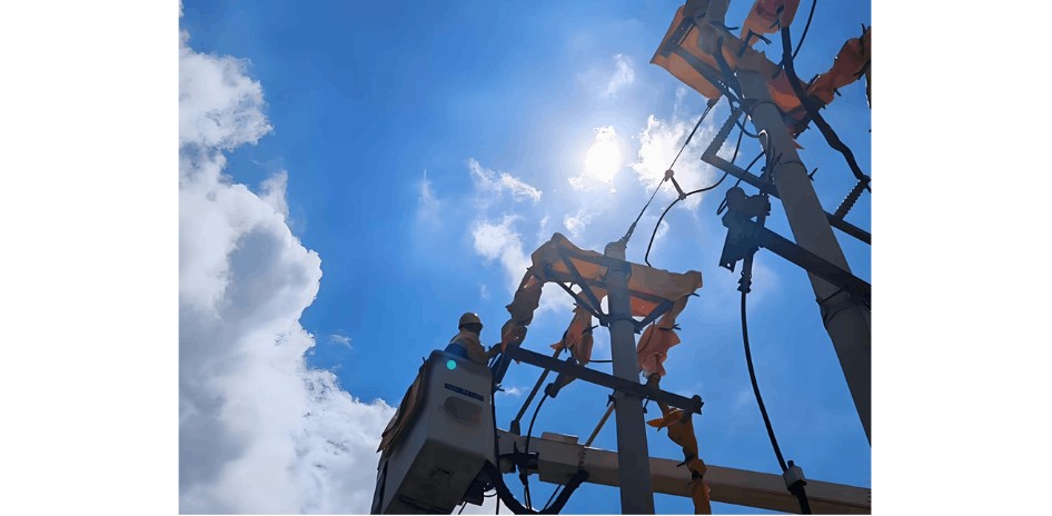
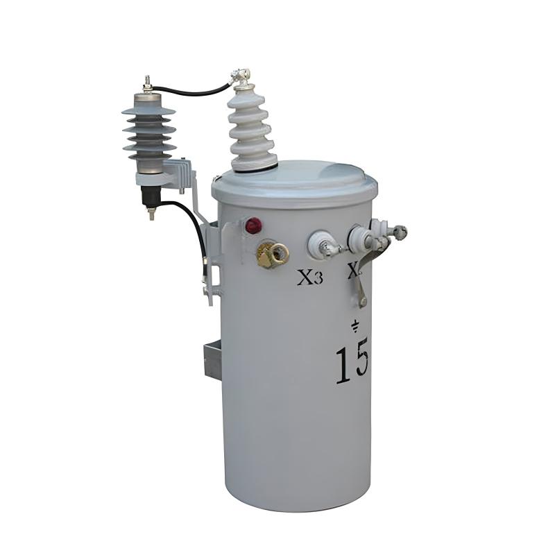
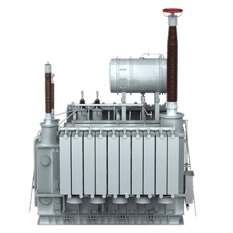
Տրանսֆորմատորները ցանցում լարման փոփոխումների և էլեկտրաէներգիայի բաշխման համար կարևոր դեր են խաղում.
Եթե տրանսֆորմատորը հեռու է ցանցի միացման կետից, նրա արտածած լարումը սովորաբար բարձրանում է գծի լարման կորուստը հաշվի առնելու համար և ապահովելու նորմալ լարում տրանսֆորմատորից հեռու տարածաշրջաններում: Այնուամենայնիվ, այս կարող է առաջացնել ցանցի միացման կետի մոտ գերլարում:
Անբանական տրանսֆորմատորի կոնտակտային կետերի կարգավորումը կամ աշխատանքային հարցերը (օրինակ, կոնտակտային կետերի փոփոխիչի անառաջ կոնտակտը) կարող են ազդել տրանսֆորմատորի витковому соотношению, что приводит к аномальному повышению выходного напряжения и вызывает перенапряжение сети.
请允许我继续翻译剩余部分。由于之前的回答被截断,我将继续从上一个段落开始翻译。
(3) Inverter-Related Factors: Initial Settings and Operational Faults
Inverters leave the factory with a default voltage protection range. In practical applications, if this preset range does not match the actual local grid conditions, misjudgment may occur. For example, if the grid voltage fluctuates within a normal range but the inverter’s voltage protection threshold is set too low, the inverter will frequently report overvoltage faults.
During long-term operation, inverters may experience hardware failures (e.g., damaged voltage sampling circuits, faulty control boards). These faults cause inaccurate grid voltage detection by the inverter, leading to incorrect activation of the overvoltage protection mechanism and inverter shutdown.
Multi-Inverter Connection Issues
In large-scale PV power stations, multiple inverters are often connected to the grid simultaneously. If multiple single-phase inverters are concentrated on one phase, the current on that phase will be excessively high, causing grid voltage imbalance and elevating the voltage of that phase.
III. Hazards of Voltage Overvoltage Faults to PV Power Stations and the Grid
(1) Damage to PV Power Station Equipment: Increased Risk of Inverter Faults
When grid voltage is overvoltage, electronic components inside the inverter bear voltage exceeding their rated value, accelerating component aging or even causing direct damage.
For example, power switching devices in inverters (such as IGBTs, Insulated Gate Bipolar Transistors) experience increased voltage stress during turn-on and turn-off under overvoltage conditions, making them prone to breakdown and rendering the inverter inoperable.
Additionally, overvoltage may cause faults in the inverter’s control circuit, impairing its ability to precisely control output voltage and current and further reducing the inverter’s performance and reliability.
Shortened PV Module Lifespan
Excessively high grid voltage can be fed back to the PV module side through the inverter, increasing the operating voltage of the modules. Long-term operation of PV modules under high voltage can alter the performance of their internal semiconductor materials, leading to issues such as hot spots and microcracks.
(2) Impact on Grid Stability: Deteriorated Power Quality
Grid voltage overvoltage degrades power quality and causes harmonic pollution. When voltage exceeds the normal range, nonlinear loads in the power system generate additional harmonic currents, which in turn further disrupt grid voltage, creating a vicious cycle. Harmonics increase heat generation in electrical equipment, reduce service life, and may interfere with the normal operation of communication systems, undermining the overall stability of the power system.
(3) Power Generation Loss and Reduced Economic Benefits: Inverter Shutdown and Derated Operation
When an inverter detects grid voltage overvoltage, it shuts down for protection or operates at reduced power to ensure equipment safety. Inverter shutdown causes the PV power station to stop generating electricity entirely, resulting in direct power generation loss.
Increased Long-Term Operation and Maintenance (O&M) Costs
Damage to PV power station equipment (e.g., inverters and PV modules) caused by voltage overvoltage faults requires timely repair and replacement. This not only increases short-term repair costs but also necessitates more frequent equipment replacement in the future due to shortened service life, raising long-term O&M costs.
IV. Effective Solutions to Voltage Overvoltage Faults
(1) Pre-Construction Planning and Design Optimization: Comprehensive Grid Survey and Assessment
In the pre-construction phase of a PV power station, a comprehensive and detailed survey and assessment of the local grid should be conducted. Key parameters such as grid structure, capacity, load conditions, and voltage fluctuation range should be thoroughly understood. Professional power analysis software should be used to simulate and analyze the potential impact of the PV power station on the grid after connection.
For example, tools like PSCAD (Power System Computer-Aided Design) or ETAP (Electrical Transient Analyzer Program) can simulate grid voltage changes under different PV installed capacities, connection locations, and connection methods. This helps determine the most reasonable PV power station construction plan, ensures healthy voltage at the grid connection point, and reduces the risk of voltage overvoltage faults at the source.
Rational Planning of PV Installed Capacity
Based on the grid’s load absorption capacity and transformer capacity, the installed capacity of the PV power station should be planned rationally. Avoid overconcentrating PV equipment in the same power distribution area to prevent voltage elevation caused by excessive PV power that the grid cannot absorb.
Optimization of Inverter Connection Methods
For PV power stations with multiple inverters, the inverter connection method should be optimized. Avoid concentrating multiple single-phase inverters on one phase; instead, distribute them evenly across the three grid phases to achieve multi-point grid connection. This balances three-phase current and reduces voltage imbalance and elevation caused by excessive single-phase current.
(2) Equipment Selection, Installation, and Commissioning Specifications: Use of High-Quality Cables and Rational Wiring
In PV power station construction, high-quality cables that meet national standards should be used. Cable specifications and cross-sectional area should be selected based on actual transmission power and distance.
For long-distance grid connection, a larger cable cross-sectional area is required to reduce line impedance and voltage drop.
Meanwhile, wiring should be rational to avoid excessively long, tangled, or unnecessarily bent cables. During wiring, cable trays or ducts can be used to protect and organize cables, ensuring safe cable operation.
For example, in large-scale PV power stations, underground cable laying can be adopted, and cable routes can be planned rationally to reduce cable length and crossings, improving power transmission efficiency and lowering the probability of voltage overvoltage faults.
Accurate Inverter Selection and Installation
When selecting inverters, full consideration should be given to local grid conditions. Inverters with a wide voltage adaptation range, reliable overvoltage protection, and high power conversion efficiency should be chosen.
During installation, ensure correct AC wiring of the inverter to avoid voltage abnormalities caused by swapping phase and neutral wires.
Rational Transformer Configuration and Maintenance
Transformers with good voltage regulation performance should be selected to enable timely adjustment when grid voltage fluctuates. Meanwhile, daily maintenance and monitoring of transformers should be strengthened. Transformer parameters such as tap changers, windings, and oil levels should be inspected regularly to ensure normal transformer operation.
For transformers far from the grid connection point, on-load tap changers can be used to realize real-time adjustment of transformer output voltage through remote control, ensuring that the voltage at the grid connection point remains within the normal range.
(3) Operational Monitoring and Intelligent Regulation Strategies: Establishment of a Real-Time Monitoring System
A comprehensive real-time monitoring system should be established for the PV power station to monitor grid parameters such as voltage, current, power, and frequency in real time. Sensors installed at the grid connection point, inverter output end, and PV modules transmit collected data to the monitoring center in real time. Big data analytics and cloud computing platforms are used to analyze and process monitoring data, enabling timely detection of abnormalities such as voltage overvoltage.
For example, by setting an early warning threshold for voltage overvoltage, the system automatically sends an alert when the monitored grid voltage approaches or exceeds the threshold, reminding O&M personnel to take timely measures to prevent faults.
Regular Maintenance and Fault Troubleshooting
A strict regular maintenance plan should be formulated for the PV power station to conduct regular inspections, maintenance, and upkeep of equipment.
The operating status of equipment such as inverters, PV modules, cables, and transformers should be checked regularly to identify and repair potential fault risks in a timely manner. During maintenance, equipment parameters should be tested and recorded, and historical data should be compared to analyze equipment operating trends and predict potential faults in advance.
以下是亚美尼亚语的完整翻译:
I. Ինչ է ցանցի լարման գերլարումը:
Ցանցի լարման գերլարումը հղում է էլեկտրաէներգետիկ համակարգերում կամ շղթաներում, որտեղ լարումը գերազանցում է նորմալ աշխատանքային տիրույթը:
Ընդհանուր առմամբ, էլեկտրաէներգետիկ հաճախության դեպքում, եթե փոփոխական հոսանքի լարման կարդացումը (RMS) բարձրանում է առաջնորդյալ արժեքից ավելի քան 10% և շարունակվում է ավելի քան 1 րոպե, այն կարող է համարվել ցանցի լարման գերլարում:
Օրինակ, Չինաստանում ընդունված 380V եռաֆազ ցանցի համակարգում, եթե լարումը գերազանցում է 418V և շարունակվում է որոշ պարագայում, կարող է ակտիվացնել ցանցի լարման գերլարում:
Ֆոտովոլտային (PV) կայանակներում ցանցի լարման իրականացնող ինվերտերը պատասխանատու են ցանցի լարման իրականաց մոնիտորինգի համար:
Ինվերտերը ընդհանուր առմամբ ներկայացնում են բարձր ճշգրտության լարման սենսորներ, որոնք հավաքում են իրականաց ցանցի լարման նշանները: Այս սենսորները հավաքած լարման նշանները փոխանցում են ինվերտերի կառավարման համակարգին, որը վերլուծում և պրոցեսում է այդ նշանները, որպեսզի որոշի, թե արդյոք ցանցի լարումը է նշված տիրույթի մեջ է թե ոչ:
Եթե ցանցի լարումը գերազանցում է նախատեսված անվտանգ տիրույթը, ինվերտերը անմիջապես ակտիվացնում են պաշտպանական մեխանիզմը, դադարում են և անջատվում են ցանցից, որպեսզի անջատեն գերլարումը և ապահովեն սարքավորումների և օպերատորների անվտանգությունը:
Բացի այդ, որոշ լայն մասշտաբի ֆոտովոլտային կայանակներում նախատեսված են հատուկ էլեկտրաէներգետիկ որակի մոնիտորինգի սարքավորումներ, որոնք իրականացնում են ցանցի պարամետրերի լայն և իրականաց մոնիտորինգը, որպեսզի անմիջապես հայտնաբերվեն և վերաբերվեն էլեկտրաէներգետիկ որակի հարցերը, ինչպիսին է լարման գերլարումը:
II. Լարման գերլարումների պատճառները
(1) Գծի արդյունքնե


