Feeder Protection

04/28/2025

Feeder Protection

Definition

Feeder protection refers to safeguarding electrical feeders against faults to ensure the uninterrupted power supply of the grid. Feeders transmit electrical energy from substations to the load end. Given their crucial role in the power distribution network, protecting feeders from various types of faults is of utmost importance. The primary requirements for feeder protection are as follows:

  • Selective Tripping: During a short - circuit event, only the circuit breaker closest to the fault should open, while all other circuit breakers remain closed. This minimizes the impact on the power supply and reduces the scope of outages.

  • Backup Protection: In the event that the circuit breaker nearest to the fault fails to open, adjacent circuit breakers must act as backup protection to isolate the faulty section. This redundancy ensures the reliability of the overall system.

  • Optimal Relay Response: The operating time of the protection relays should be minimized to maintain system stability while preventing unnecessary tripping of healthy circuits. This balance is essential for efficient fault handling.

Time - Graded Protection

Time - graded protection is a scheme that involves setting the operating times of relays in a sequential manner. This approach ensures that when a fault occurs, only the smallest possible portion of the electrical system is isolated, thereby minimizing disruption to the overall power supply. The practical applications of time - graded protection are described below.

Protection of Radial Feeders

A radial power system is characterized by unidirectional power flow, moving from the generator or supply source towards the load end. However, this system has a significant drawback: in the event of a fault, maintaining the continuity of power supply at the load end becomes challenging.

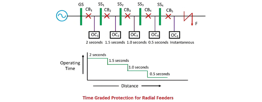
In a radial system where multiple feeders are connected in series, as illustrated in the figure, the goal is to isolate the smallest possible section of the system when a fault occurs. Time - graded protection effectively achieves this objective. The over - current protection system is configured such that the farther a relay is located from the generating station, the shorter its operating time. This hierarchical time - setting mechanism ensures that faults are cleared as close to the source of the problem as possible, reducing the impact on the rest of the system.

image.png

When a fault occurs on SS4, relay OC5 should be the first to operate, rather than any other relay. This means that the operating time of relay OC4 must be shorter than that of relay OC3, and so on. This clearly demonstrates the necessity of proper time - grading for these relays. The minimum time interval between two adjacent circuit breakers is determined by the sum of their own clearance times and a small safety margin.

For commonly used circuit breakers, the minimum discriminating time between breakers during adjustment is approximately 0.4 seconds. The time settings for relays OC1, OC2, OC3, OC4, and OC5 are set as 0.2 seconds, 1.5 seconds, 1.5 seconds, 1.0 seconds, 0.5 seconds, and instantaneous respectively. In addition to the time - grading system, it is crucial that the operation time for severe faults is minimized. This can be achieved by connecting time - limiting fuses in parallel with the trip coils.

Protection of Parallel Feeders

Parallel feeder connections are primarily employed to ensure continuous power supply and distribute the load. When a fault occurs in a protected feeder, the protective device will identify and isolate the faulty feeder, allowing the remaining feeders to immediately assume the increased load.

One of the simplest and most effective protection methods for relays in parallel feeder systems involves using time - graded overload relays with inverse time characteristics at the sending end, combined with instantaneous reverse - power or directional relays at the receiving end, as depicted in the figure below. This configuration enables quick and accurate fault detection and isolation, enhancing the overall reliability and stability of the parallel feeder system.

image.png

When a severe fault F occurs on any one of the lines, power will flow into the fault from both the sending and receiving ends of the line. As a result, the direction of power flow through the relay at point D will reverse, causing the relay to open.

The excessive current will then be confined to point B until its overload relay activates and trips the circuit breaker. This action completely isolates the faulty feeder, enabling power supply to continue through the healthy feeder. However, this method is only effective when the fault is severe enough to reverse the power flow at D. Therefore, differential protection is incorporated in addition to overload protection at both ends of the line to enhance the reliability of the protection system.

Protection of Ring Main System

The ring main system is an interconnection network that links a series of power stations via multiple routes. In this system, the direction of power flow can be adjusted as needed, especially when interconnections are utilized.

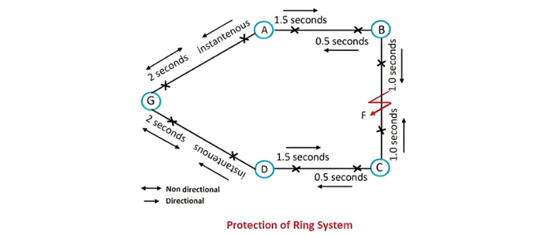
The basic schematic of such a system is illustrated in the figure below, where G represents the generating station, and A, B, C, and D denote substations. At the generating station, power flows in a single direction, so time - lag overload relays are not required. Time - graded overload relays are installed at the ends of the substations. These relays will only trip when an overload current flows away from the substations they are protecting, ensuring selective fault isolation and maintaining the stability of the ring main system.

image.png

When traversing the ring in the direction of GABCD, the relays on the far side of each station are configured with progressively decreasing time lags. At the generating station, the time lag is set to 2 seconds; at stations A, B, and C, the settings are 1.5 seconds, 1.0 second, and 0.5 second respectively, while the relay at the next relevant point operates instantaneously. Similarly, when moving around the ring in the opposite direction, the relays on the outgoing sides are set according to a corresponding time - lag pattern.

In the event of a fault occurring at point F, power flows into the fault via two distinct paths: ABF and DCF. The relays that are triggered are those situated between substation B and the fault point F, as well as between substation C and the fault point F. This configuration ensures that a fault on any given section of the ring main system will prompt only the relevant relays on that specific section to operate. Consequently, the unaffected sections of the system can continue to function without interruption, maintaining the integrity and reliability of the overall power distribution network.

The Electricity Encyclopedia is dedicated to accelerating the dissemination and application of electricity knowledge and adding impetus to the development and innovation of the electricity industry.

What is the difference between a dielectric and an insulator?
Dielectrics and insulators are distinguished primarily by their applications. One of the main differences is that a dielectric can store electrical energy by becoming polarized in an electric field, whereas an insulator resists the flow of electrons to prevent current conduction. Other key differences between them are outlined in the comparison chart below.Definition of DielectricA dielectric material is a type of insulator that contains few or no free electrons. When subjected to an electric fi
08/30/2025
Transformer Connection Sections
Transformer Connection DesignationsThe transformer connection designation indicates the winding connection method and the phase relationship between the line voltages of the primary and secondary windings. It consists of two parts: letters and a number. The letters on the left denote the connection configurations of the high-voltage and low-voltage windings, while the number on the right is an integer from 0 to 11.This number represents the phase shift of the low-voltage winding's line voltage r
08/15/2025
Automatic Reclosing Scheme in Transmission Systems
Automatic Reclosing Scheme for Transmission SystemsThe automatic reclosing system is a series-connected network designed to reduce operating costs and enhance network reliability. Extra-high voltage (EHV) transmission lines are used to transmit large amounts of power, on the order of thousands of megawatts (MW), and therefore should not be interrupted at all costs. Although faults on these overhead lines are common, the power transmitted through them should not be interrupted for long periods du
08/07/2025
Transformer operation and maintenance
Transformer Operating TemperatureDuring operation, transformers generate copper losses and iron losses, both of which are converted into heat, causing the transformer’s temperature to rise. Most transformers in China use Class A insulation. Due to heat transfer characteristics, significant temperature differences exist between different components during operation: winding temperature is the highest, followed by the core, and then the temperature of the insulating oil (with upper-layer oil being
07/31/2025
Inquiry
Download
IEE-Business is dedicated to serving the personnel in the global power industry.
Join IEE-Business, not only can you discover power equipment and power knowledge, but also canhnd like - minded friends!