• Product
  • Suppliers
  • Manufacturers
  • Solutions
  • Free tools
  • Knowledges
  • Experts
  • Communities
Search


Understanding Transformer Primary and Secondary Coils: Structure and Function

Rockwell
Field: Manufacturing
China

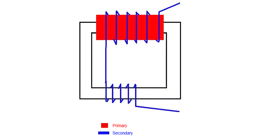
The primary and secondary coils are two fundamental components of a transformer, enabling the transmission and transformation of electrical energy through the principle of electromagnetic induction. The primary coil receives high-voltage current from the input source and generates a varying magnetic field, while the secondary coil, influenced by this magnetic field, produces a corresponding output voltage. Their interaction allows the transformer to perform voltage conversion, facilitating efficient power transmission and distribution.

Position and Structure

In a transformer, both coils are typically wound around a common iron core to ensure effective magnetic coupling through electromagnetic induction. The primary coil is connected to the input side, and the secondary coil to the output side. They are electrically isolated from each other by insulation materials and the core structure, preventing direct current flow.

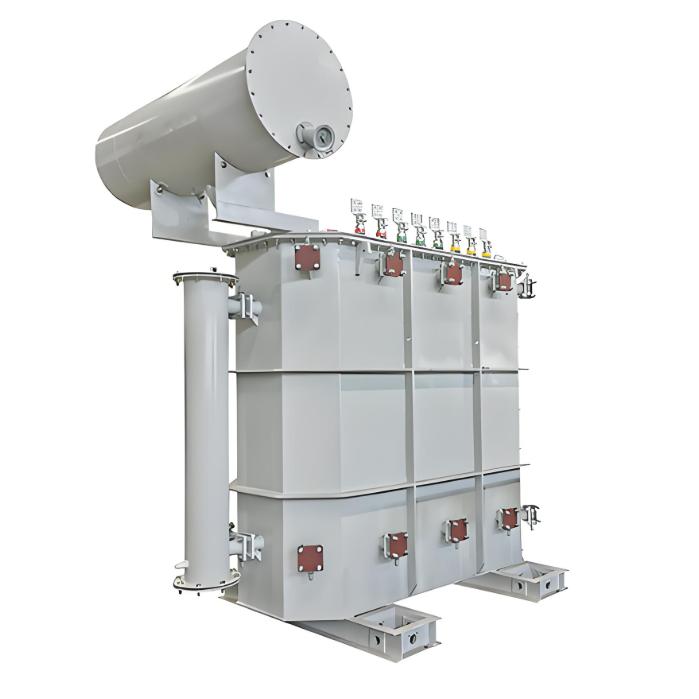
  • Primary Coil: Located on the high-voltage side, the primary coil consists of many turns of insulated conductor wound on one side of the iron core. It receives the input current and generates a time-varying magnetic field in the core.

  • Secondary Coil: Positioned on the low-voltage side, the secondary coil has fewer turns of insulated conductor wound on the other side of the core. It captures the changing magnetic flux and delivers the transformed (stepped-up or stepped-down) voltage at the output.

Principle of Voltage Transformation

Voltage transformation in a transformer is governed by Faraday’s law of electromagnetic induction and Lenz’s law.

  • Primary Coil: When alternating current flows through the primary coil, it produces a continuously changing magnetic field in the iron core. This varying flux is essential for inducing voltage in the secondary coil.

  • Secondary Coil: The changing magnetic flux from the primary induces an electromotive force (EMF) in the secondary coil according to Faraday’s law. This induced EMF drives current through the load connected to the output, delivering the transformed electrical energy.

Turns Ratio and Voltage Transformation Ratio

The voltage transformation ratio is directly determined by the turns ratio between the primary and secondary coils. According to electromagnetic induction theory, the induced EMF in each coil is proportional to its number of turns.

  • In a step-up transformer, the secondary coil has more turns than the primary, resulting in a higher output voltage.

  • In a step-down transformer, the secondary coil has fewer turns than the primary, yielding a lower output voltage.

The turns ratio is precisely designed to meet specific voltage conversion requirements. Thus, the relationship between the number of turns and the voltage ratio is fundamental to the transformer’s operation, defining its performance and application.

Give a tip and encourage the author!

Recommended

Impact of DC Bias in Transformers at Renewable Energy Stations Near UHVDC Grounding Electrodes
Impact of DC Bias in Transformers at Renewable Energy Stations Near UHVDC Grounding ElectrodesWhen the grounding electrode of an Ultra-High-Voltage Direct Current (UHVDC) transmission system is located close to a renewable energy power station, the return current flowing through the earth can cause a rise in ground potential around the electrode area. This ground potential rise leads to a shift in the neutral-point potential of nearby power transformers, inducing DC bias (or DC offset) in their
01/15/2026
HECI GCB for Generators – Fast SF6 Circuit Breaker
1.Definition and Function1.1 Role of the Generator Circuit BreakerThe Generator Circuit Breaker (GCB) is a controllable disconnect point located between the generator and the step-up transformer, serving as an interface between the generator and the power grid. Its primary functions include isolating generator-side faults and enabling operational control during generator synchronization and grid connection. The operating principle of a GCB is not significantly different from that of a standard c
01/06/2026
Distribution Equipment Transformer Testing, Inspection, and Maintenance
1.Transformer Maintenance and Inspection Open the low-voltage (LV) circuit breaker of the transformer under maintenance, remove the control power fuse, and hang a “Do Not Close” warning sign on the switch handle. Open the high-voltage (HV) circuit breaker of the transformer under maintenance, close the grounding switch, fully discharge the transformer, lock the HV switchgear, and hang a “Do Not Close” warning sign on the switch handle. For dry-type transformer maintenance: first clean the porcel
12/25/2025
How to Test Insulation Resistance of Distribution Transformers
In practical work, insulation resistance of distribution transformers is generally measured twice: the insulation resistance between thehigh-voltage (HV) windingand thelow-voltage (LV) winding plus the transformer tank, and the insulation resistance between theLV windingand theHV winding plus the transformer tank.If both measurements yield acceptable values, it indicates that the insulation among the HV winding, LV winding, and transformer tank is qualified. If either measurement fails, pairwise
12/25/2025
Related Products
Send inquiry
+86
Click to upload file

IEE Business will not sell or share your personal information.

Download
Get the IEE Business Application
Use the IEE-Business app to find equipment, obtain solutions, connect with experts, and participate in industry collaboration anytime, anywhere—fully supporting the development of your power projects and business.