• Product
  • Suppliers
  • Manufacturers
  • Solutions
  • Free tools
  • Knowledges
  • Experts
  • Communities
Search


Can a 50Hz-Designed Power Transformer Operate on a 60Hz Grid? Key Performance Changes Explained

Vziman
Field: Manufacturing
China

Can a 50Hz-Designed Power Transformer Operate on 60Hz Grid?

If a power transformer is designed and built for 50Hz, can it run on a 60Hz grid? If so, how do its key performance parameters change?

Key Parameter Changes

  • Short-Circuit Impedance:For a given transformer (same voltage and capacity), short-circuit impedance is proportional to frequency. Thus, a 50Hz-designed unit operating at 60Hz sees a 20% increase—higher frequency intensifies alternating leakage field opposition to current.

  • No-Load Loss :From U = 4.44fNBmS, with constant voltage, 50Hz→60Hz lowers Bm to 0.83x. Though 60Hz silicon steel unit loss is ~1.31x that at 50Hz, reduced Bm dominates, cutting overall no-load loss.

  • Load Loss: Load loss includes DC resistance loss (frequency-independent), eddy current loss∝ f2), and stray loss (≈∝ f2). Thus, 50Hz→60Hz increases load loss, with magnitude depending on DC resistance loss proportion.

  • Temperature Rise:While no-load loss drops, load loss (typically larger) rises, increasing total loss. This elevates average/top-oil temperatures; higher winding eddy loss also raises average/hot-spot winding temperatures.

Quantitative Case Study

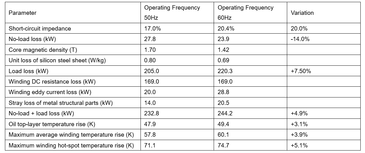
To quantify these trends, calculations for a 50Hz-designed 63MVA/110kV transformer are compared below.

Conclusion

In summary, a power transformer designed and manufactured for a rated frequency of 50Hz can fully operate on a 60Hz grid under the premise that the primary side excitation voltage and transmission capacity remain unchanged. It should be noted that in this case, the total loss of the transformer will increase by approximately 5%, which in turn leads to a rise in the top-oil temperature rise and the average winding temperature rise. In particular, the winding hot-spot temperature rise may increase by more than 5%.

If the transformer already has a certain margin in terms of winding hot-spot temperature rise and the hot-spot temperature rise of metal structural components (such as clamps, riser flanges, etc.), such operation is completely acceptable. However, if the winding hot-spot temperature rise or that of metal structural components is already close to the limit of exceeding the standard, whether long-term operation under such conditions is acceptable requires a case-by-case analysis.

Give a tip and encourage the author!

Recommended

How to Judge, Detect and Troubleshoot Transformer Core Faults
1. Hazards, Causes, and Types of Multi-Point Grounding Faults in Transformer Cores1.1 Hazards of Multi-Point Grounding Faults in the CoreUnder normal operation, a transformer core must be grounded at only one point. During operation, alternating magnetic fields surround the windings. Due to electromagnetic induction, parasitic capacitances exist between the high-voltage and low-voltage windings, between the low-voltage winding and the core, and between the core and the tank. The energized windin
01/27/2026
A Brief Discussion on the Selection of Grounding Transformers in Boost Stations
A Brief Discussion on the Selection of Grounding Transformers in Boost StationsThe grounding transformer, commonly referred to as "grounding transformer," operates under the condition of being no-load during normal grid operation and overloaded during short-circuit faults. According to the difference in filling medium, common types can be divided into oil-immersed and dry-type; according to phase number, they can be classified into three-phase and single-phase grounding transformers. The groundi
01/27/2026
Impact of DC Bias in Transformers at Renewable Energy Stations Near UHVDC Grounding Electrodes
Impact of DC Bias in Transformers at Renewable Energy Stations Near UHVDC Grounding ElectrodesWhen the grounding electrode of an Ultra-High-Voltage Direct Current (UHVDC) transmission system is located close to a renewable energy power station, the return current flowing through the earth can cause a rise in ground potential around the electrode area. This ground potential rise leads to a shift in the neutral-point potential of nearby power transformers, inducing DC bias (or DC offset) in their
01/15/2026
HECI GCB for Generators – Fast SF6 Circuit Breaker
1.Definition and Function1.1 Role of the Generator Circuit BreakerThe Generator Circuit Breaker (GCB) is a controllable disconnect point located between the generator and the step-up transformer, serving as an interface between the generator and the power grid. Its primary functions include isolating generator-side faults and enabling operational control during generator synchronization and grid connection. The operating principle of a GCB is not significantly different from that of a standard c
01/06/2026
Related Products
Send inquiry
+86
Click to upload file

IEE Business will not sell or share your personal information.

Download
Get the IEE Business Application
Use the IEE-Business app to find equipment, obtain solutions, connect with experts, and participate in industry collaboration anytime, anywhere—fully supporting the development of your power projects and business.