What is GIS (Gas-Insulated Switchgear)? Features, Types, and Applications

What is GIS Equipment?
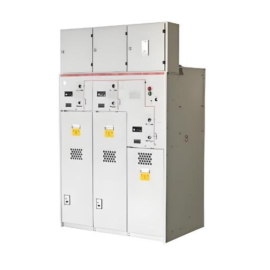
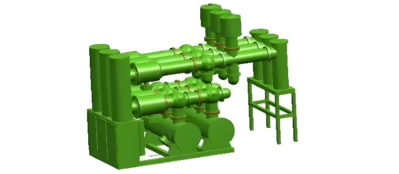
GIS is the English abbreviation for Gas Insulated Switchgear, which is fully translated into Chinese as Gas-Insulated Metal-Enclosed Switchgear. It typically uses sulfur hexafluoride (SF6) gas as the insulating and arc-quenching medium. GIS integrates, through optimized design, the main primary equipment in a substation—excluding the transformer—such as circuit breakers (CB), disconnectors (DS), earthing switches (ES/FES), busbars (BUS), current transformers (CT), voltage transformers (VT), surge arresters (LA), cable terminations, and incoming/outgoing line bushings—into a single sealed metallic enclosure, forming an integrated unit.
Currently, the voltage rating range of GIS equipment is extensive, spanning from 72.5 kV to 1200 kV.
Characteristics of GIS Equipment
SF6 gas possesses excellent dielectric strength, arc-quenching capability, and chemical stability. As a result, GIS equipment features compact size, minimal footprint, high operational reliability, long maintenance intervals, and strong electromagnetic interference resistance. Additionally, due to its fully enclosed structure, internal components are protected from external environmental factors (such as dust, moisture, and salt fog), ensuring stable operation, low electromagnetic noise, and reduced maintenance workload.
However, the dielectric performance of SF6 gas is highly sensitive to electric field uniformity. Internal defects such as conductor burrs, metallic particles, or assembly flaws can easily lead to partial discharge or even insulation breakdown. Furthermore, the sealed structure of GIS makes internal fault diagnosis and maintenance complex, with limited diagnostic tools. Poor sealing may also result in water ingress or gas leakage, compromising equipment safety.
Types of Electrical Contacts in GIS Conduction Circuits
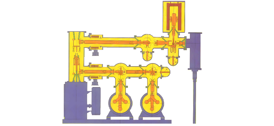
The conduction circuit in GIS consists of multiple components and can be classified into three types based on contact method:
Fixed Contact: Electrical connections secured by bolts or other fasteners, with no relative movement during operation, such as the connection between a busbar and a basin-type insulator.
Separable Contact: Electrical contacts that can be opened or closed during operation, such as the contacts in circuit breakers and disconnectors.
Sliding or Rolling Contact: Contacts that allow relative sliding or rolling between contact surfaces but cannot be separated, such as intermediate contacts in switchgear.
Introduction to HGIS
In addition to GIS, there is another type called HGIS (Hybrid Gas-Insulated Switchgear), a hybrid gas-insulated switchgear. HGIS does not include components such as busbars, busbar voltage transformers, or busbar surge arresters, resulting in a simpler structure. It is suitable for harsh environments or locations with space constraints and offers greater flexibility in layout.
Classification of GIS Equipment
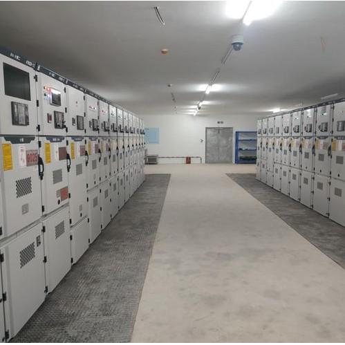
By Installation Location: Indoor and outdoor types.
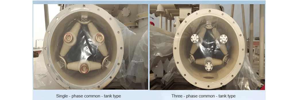
By Structure: Single-phase single-enclosure and three-phase common-enclosure. Generally, busbars at voltage levels of 110 kV and below can adopt the three-phase common-enclosure design, while voltage levels of 220 kV and above typically use the single-phase single-enclosure design to reduce the risk of phase-to-phase faults.
Basic Operating Principles
Under normal conditions, GIS circuit breakers and disconnectors are primarily operated remotely. The "Remote/Local" selector switch should be set to the "Remote" position.
Earthing switches can only be operated locally. During operation, the "Disconnector/Earthing Switch" selector switch must be switched to the "Local" position.
All operations must follow programmed procedures. The "Interlock Release Switch" on the control cabinet must remain in the "Interlock" position. The unlocking key, along with the microcomputer anti-misoperation unlocking key, must be sealed and managed strictly according to regulations.
Basic Operational Requirements
For indoor SF6 equipment rooms frequently accessed by personnel, ventilation should be performed at least once per shift for no less than 15 minutes, with air exchange volume exceeding 3–5 times the room volume. Air exhaust outlets should be located at the lower part of the room. For areas not frequently entered, ventilation for 15 minutes is required before entry.
During operation, the induced voltage on accessible parts of the GIS enclosure and structure should not exceed 36 V under normal conditions.
Temperature Rise Limits:
Easily accessible parts: no more than 30 K;
Parts easily touched but not contacted during operation: no more than 40 K;
Rarely accessible individual parts: no more than 65 K.
SF6 switchgear should be inspected at least once daily. For unattended substations, inspections should be conducted according to established procedures. Inspections should focus on visual checks for abnormalities such as unusual sounds, leaks, or abnormal indications, with records maintained accordingly.