• Product
  • Suppliers
  • Manufacturers
  • Solutions
  • Free tools
  • Knowledges
  • Experts
  • Communities
Search


Three-Tier Power Distribution System in a Newly Constructed Residential Area

Rockwell
Field: Manufacturing
China

In a newly constructed residential area, a 10kV power line is introduced into the substation. After stepping down the voltage through the transformer's low-voltage side (0.4kV), power distribution is achieved through three levels of distribution boxes: the main distribution board, secondary distribution boards, and tertiary distribution boards.

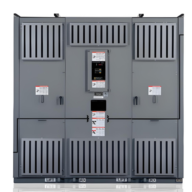
Main Distribution Board

  • Serves as the primary distribution point for the entire project, directly connected to the transformer providing 0.4kV power.

  • Does not supply power directly to end-use equipment but acts as a centralized power distribution hub.

  • Includes components such as isolating switches, circuit breakers, and Residual Current Devices (RCDs) to ensure overall circuit safety.

Secondary Distribution Boards

  • Designed for specific buildings or floors, responsible for distributing three-phase power.

  • Connects to motors or other heavy loads, utilizing larger capacity three-phase circuit breakers to ensure safe operation.

  • Emphasizes protective measures like dual-door protection, durable coatings, and rainproof designs suitable for outdoor environments, ensuring electrical safety during the intermediate stages.

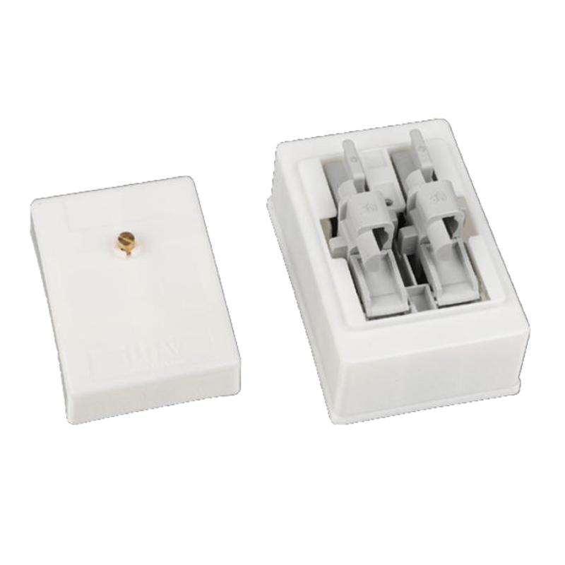
Tertiary Distribution Boards

  • Ultimately connects to home systems or specific pieces of equipment, supplying 220V single-phase power.

  • Implements strict safety standards, such as "one device, one circuit breaker, one RCD, one box," ensuring independent circuit protection for each device.

  • May include fixed or portable boxes to ensure electrical safety and adhere to a "two-layer protection" strategy, meaning RCDs at both the tertiary (device level) and secondary (area level).

This three-tier distribution system structure — with the main distribution board acting as the primary delivery point, secondary distribution boards serving as intermediate power hubs, and tertiary distribution boards directly supplying end-use equipment — ensures effective power management, high safety, and reliability in complex electrical systems, especially suited for the power needs of construction sites or large projects.

Give a tip and encourage the author!

Recommended

HECI GCB for Generators – Fast SF6 Circuit Breaker
1.Definition and Function1.1 Role of the Generator Circuit BreakerThe Generator Circuit Breaker (GCB) is a controllable disconnect point located between the generator and the step-up transformer, serving as an interface between the generator and the power grid. Its primary functions include isolating generator-side faults and enabling operational control during generator synchronization and grid connection. The operating principle of a GCB is not significantly different from that of a standard c
01/06/2026
Distribution Equipment Transformer Testing, Inspection, and Maintenance
1.Transformer Maintenance and Inspection Open the low-voltage (LV) circuit breaker of the transformer under maintenance, remove the control power fuse, and hang a “Do Not Close” warning sign on the switch handle. Open the high-voltage (HV) circuit breaker of the transformer under maintenance, close the grounding switch, fully discharge the transformer, lock the HV switchgear, and hang a “Do Not Close” warning sign on the switch handle. For dry-type transformer maintenance: first clean the porcel
12/25/2025
How to Test Insulation Resistance of Distribution Transformers
In practical work, insulation resistance of distribution transformers is generally measured twice: the insulation resistance between thehigh-voltage (HV) windingand thelow-voltage (LV) winding plus the transformer tank, and the insulation resistance between theLV windingand theHV winding plus the transformer tank.If both measurements yield acceptable values, it indicates that the insulation among the HV winding, LV winding, and transformer tank is qualified. If either measurement fails, pairwise
12/25/2025
Design Principles for Pole-Mounted Distribution Transformers
Design Principles for Pole-Mounted Distribution Transformers(1) Location and Layout PrinciplesPole-mounted transformer platforms should be located near the load center or close to critical loads, following the principle of “small capacity, multiple locations” to facilitate equipment replacement and maintenance. For residential power supply, three-phase transformers may be installed nearby based on current demand and future growth projections.(2) Capacity Selection for Three-Phase Pole-Mounted Tr
12/25/2025
Related Products
Send inquiry
+86
Click to upload file

IEE Business will not sell or share your personal information.

Download
Get the IEE Business Application
Use the IEE-Business app to find equipment, obtain solutions, connect with experts, and participate in industry collaboration anytime, anywhere—fully supporting the development of your power projects and business.