Thermal Optimization Design for Control Cabinets of Pad-Mounted Transformers in Offshore Wind Turbines

Global energy transition boosts offshore wind power, yet complex marine environments challenge turbine reliability. The heat - dissipation of pad - mounted transformer control cabinets (PMTCCs) is critical—undissipated heat causes component damage. Optimizing PMTCC heat dissipation improves turbine efficiency, but research mostly focuses on onshore wind farms, neglecting offshore ones. Thus, design PMTCCs for offshore conditions to enhance safety.
1 PMTCC Heat - Dissipation Optimization
1.1 Add Heat - Dissipation Devices
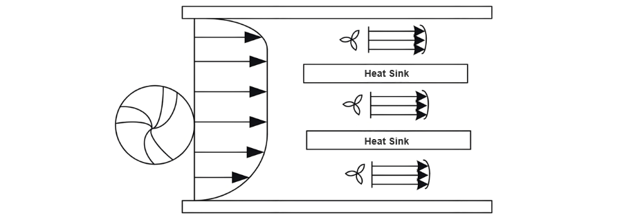
For offshore PMTCCs, add/optimize fully - sealed heat - dissipation devices to resist salt spray/moisture. Installed beside transformers, connected via special interfaces, they form efficient cooling loops. Airflow in devices: see Fig. 1.
Due to the specificities of the maritime climate in offshore wind farms, such as large temperature fluctuations, high humidity, and salt spray corrosion, more stringent requirements are posed on the heat dissipation performance of transformer control cabinets. To achieve precise optimization of heat sink design, this study innovatively combines ANSYS with MATLAB, leveraging genetic algorithms to optimize the width parameters of heat sinks.
Owing to the limitations of ANSYS' built-in parametric programming language in directly integrating optimization algorithms, MATLAB is adopted as an intermediary. Through the development of an ANSYS secondary development interface, a seamless connection between ANSYS and MATLAB is realized. It is assumed that the total area of the heat sink is 0.36 m², and the relationship between the back width az and the side edge width ac of the heat sink is defined as:

Through detailed calculations and simulations, the optimal back width of the heat sink is determined to be 0.235 m, with the widths of the two side heat sinks adjusted to 1.532 m accordingly. This optimization not only maintains the total area of the heat sink but also enhances its heat dissipation performance.
1.2 Forced Air Cooling Technology
Forced air cooling uses fans to accelerate air circulation, expanding temperature differences via air convection to enhance heat dissipation. It controls cabinet temperature safely but faces frictional/local losses in ducts. Optimizations include expanding duct width from 100 to 120 mm and reducing hydraulic diameter, minimizing energy loss and improving efficiency. Cooled oil returns to the tank through bottom pipes, forming a closed-loop for dual cooling. See Figure 2 for circulation.
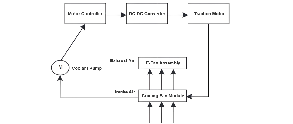
To optimize heat dissipation, an Oil Natural Air Forced (ONAF) cooling mode is selected. Fans drive air flow to make cooling air flow from bottom to top, effectively covering the entire surface of the radiator.
1.3 Optimization of Inlet and Outlet in Main Transformer Chamber
Based on the power loss of the transformer control cabinet and the expected temperature difference between the inlet and outlet, the required air flow is calculated using thermodynamics. The formula for air flow V is:

In the formula:
Given the potential decline in ventilation efficiency, the measured air flow rate is set to 1.6V. The formula for calculating the effective inlet area A is:

Where v represents the air velocity at both the inlet and outlet. After clarifying the power loss of the transformer control cabinet and determining the expected temperature difference between the inlet and outlet, the required air flow V is calculated using thermodynamic principles. Finally, the specific dimensions of the inlet and outlet are designed based on the air flow V:
Analysis of the correlation between inlet pressure loss and opening area reveals that increasing the opening area can effectively reduce gas pressure loss, thereby improving heat dissipation efficiency. On the premise of ensuring the structural strength of the control cabinet, the inlet opening area is set to 0.066 m². To enhance the effective ventilation area, a method combining grilles and louver covers is adopted to increase ventilation passages while preventing the intrusion of dust and rain. In the lower part of the main transformer chamber, an additional air inlet window is installed approximately 40 cm above the ground to further expand the inlet area.
Based on the principle of bottom air intake and top air exhaust, the layout of the inlet and outlet is optimized. The inlet is set at the lower part of the main transformer chamber, and the outlet is located at the upper part, forming natural convection. This allows hot air to rise smoothly and be discharged from the outlet, while cold air enters from the inlet, creating an effective air circulation to improve heat dissipation efficiency.
1.4 Control Cabinet Structure Optimization
To address the unique challenges of salt, humidity, and corrosive substances in offshore wind farms, high-performance anti-corrosion materials and advanced sealing technologies are employed to enhance the overall protection of the control cabinet.
Enhanced Heat Dissipation Design:
Cable Entry and Airflow Optimization:
These optimizations result in a structured, well-segregated cable layout that enhances both thermal management and system reliability.
2 Experimental Verification
2.1 Experimental Setup
To validate the feasibility of the heat dissipation design, an experimental platform was constructed to comprehensively simulate the offshore wind farm environment. Two fans were employed to replicate offshore wind speeds and directions. The experimental equipment is listed in Table 1.
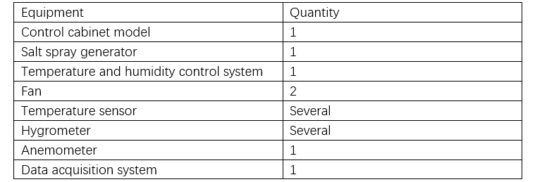
To simulate the offshore wind farm environment, when using fans to mimic wind speed and direction, attention should be paid to wind speed uniformity and direction diversity. Uniform wind speed is crucial for accurate evaluation of the control cabinet's heat dissipation performance, and diverse wind directions can more comprehensively simulate offshore wind direction changes. Thus, during the experiment, fans need to be precisely controlled to ensure wind speed and direction match the actual offshore wind farm characteristics.
2.2 Experimental Results and Analysis
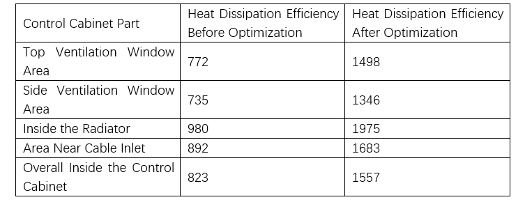
After optimizing the heat dissipation of the offshore wind farm wind turbine box - type transformer control cabinet, the heat dissipation efficiency of different parts of the control cabinet before and after optimization was recorded, as shown in Table 2.
2.3 Results and Discussion
Based on the experimental data in Table 2, the heat dissipation efficiency of the offshore wind turbine pad-mounted transformer control cabinet shows significant improvements after optimization:
3 Conclusion
This study analyzed the impact of the offshore wind farm’s harsh environment on control cabinet heat dissipation. Guided by heat transfer principles, a targeted optimization scheme was proposed and validated experimentally. The optimized design not only improves heat dissipation efficiency and reduces internal temperatures but also enhances corrosion resistance and extends service life. These measures provide robust technical support for the sustainable operation of offshore wind farms.


