
Duniya na kawo karfi don inganta aiki masu zafi, amma yankin ruwa mai zurfi ya ba da abubuwa ga kyau. Zafi - tattalin wahala kan pad - mounted transformer control cabinets (PMTCCs) shi ne mai muhimmanci—zafi bai haifar da dabbobi. Inganta PMTCC zafi - tattalin wahala yana taimaka wajen tsarkar hanyoyin turbin, amma bangaren bayanai ta gudanar da waɗannan kungiyoyin zafi na kasa, muna ƙarin da suka ce waɗannan ruwan. Saboda haka, dole PMTCCs ga yanayin ruwa don inganta cin kasa.
1 PMTCC Zafi - Tattalin Wahala Mai Yawa
1.1 Aika Zafi - Tattalin Wahala
Don PMTCC na ruwa, aika/inganta zafi - tattalin wahala mai sauƙa da sauƙa don daɓe da zuba/maya. An aika su cikin turari na transformasi, tun daga hasken kayan abubuwa, sun dogara tsaunukan tattalin wahala mai kyau. Airflow a cikin kayan abubuwa: titta Fig. 1.
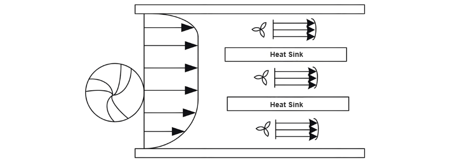
Saboda mutane da yankin ruwa na waɗannan kungiyoyin zafi na ruwa, kamar hawan sauki da ke faru, maya mai yawa, da zuba mai sauƙa, an fi sanya masu zafi - tattalin wahala mai kyau ga kabara. Don samun inganta masu zafi mai kyau, wannan bayanin ya kunshi ANSYS da MATLAB, tare da alamomin genetika don inganta parametosu na zafi.
Saboda haddadin ANSYS na built-in parametric programming language wanda ba a iya kula da alamomin inganta direkta, an yi amfani da MATLAB a matsayin mai faɗa. Tun daga ƙofar ANSYS secondary development interface, ana yi takarda mai sauƙa daga ANSYS zuwa MATLAB. Ana ɗauke cewa mafarin zafi ita ce 0.36 m², da naɗa a zafi - back width az da side edge width ac na zafi:

Naɗa a cikin rubutu da takarda, an sami zafi - back width da ke da ƙwarewa 0.235 m, da zafi - side widths da suka ɗaukar da 1.532 m. Wannan inganta tana da zafi - tattalin wahala ko kuma tana da zafi - tattalin wahala.
1.2 Teknologi Forced Air Cooling
Forced air cooling tana amfani da fans don sarrafa tattalin zafi, tana daɗe masu sauki da kuma tana inganta zafi - tattalin wahala. Yana kontrola tasirin kasa da kyau, amma tana da abubuwa da ƙarfin ducts. Ingantata cuta daɗe duct width daga 100 zuwa 120 mm da kuma kawo da hydraulic diameter, tana daɗe energy loss da kuma tana inganta efficiency. Zafi - oil tana zo zuwa tank through bottom pipes, tana dogara tsaunukan tattalin wahala. Titta Figure 2 don tattalin zafi.
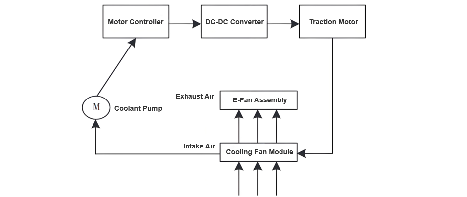
Don inganta zafi - tattalin wahala, an zaɓe Oil Natural Air Forced (ONAF) cooling mode. Fans tana saukar da airflow don tattalin zafi - airflow from bottom to top, tana daɗe masu surface of the radiator.
1.3 Inganta Inlet and Outlet in Main Transformer Chamber
Ta hanyar kusa da power loss of the transformer control cabinet da kuma expected temperature difference between the inlet and outlet, ana samun airflow required using thermodynamics. Formula for airflow V ita ce:

A cikin formula:
Saboda potential decline in ventilation efficiency, measured airflow rate ita ce 1.6V. Formula for calculating effective inlet area A ita ce:

Idan v itace velocity at both the inlet and outlet. Ba a cikin kusa da power loss of the transformer control cabinet da kuma determining the expected temperature difference between the inlet and outlet, airflow required V ita ce samun using thermodynamic principles. Finally, specific dimensions of the inlet and outlet are designed based on the airflow V:
Analysis of the correlation between inlet pressure loss and opening area reveals that increasing the opening area can effectively reduce gas pressure loss, thereby improving heat dissipation efficiency. On the premise of ensuring the structural strength of the control cabinet, the inlet opening area is set to 0.066 m². To enhance the effective ventilation area, a method combining grilles and louver covers is adopted to increase ventilation passages while preventing the intrusion of dust and rain. In the lower part of the main transformer chamber, an additional air inlet window is installed approximately 40 cm above the ground to further expand the inlet area.
Based on the principle of bottom air intake and top air exhaust, the layout of the inlet and outlet is optimized. The inlet is set at the lower part of the main transformer chamber, and the outlet is located at the upper part, forming natural convection. This allows hot air to rise smoothly and be discharged from the outlet, while cold air enters from the inlet, creating an effective air circulation to improve heat dissipation efficiency.
1.4 Control Cabinet Structure Optimization
To address the unique challenges of salt, humidity, and corrosive substances in offshore wind farms, high-performance anti-corrosion materials and advanced sealing technologies are employed to enhance the overall protection of the control cabinet.
Enhanced Heat Dissipation Design:
Cable Entry and Airflow Optimization:
These optimizations result in a structured, well-segregated cable layout that enhances both thermal management and system reliability.
2 Experimental Verification
2.1 Experimental Setup
To validate the feasibility of the heat dissipation design, an experimental platform was constructed to comprehensively simulate the offshore wind farm environment. Two fans were employed to replicate offshore wind speeds and directions. The experimental equipment is listed in Table 1.
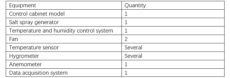
To simulate the offshore wind farm environment, when using fans to mimic wind speed and direction, attention should be paid to wind speed uniformity and direction diversity. Uniform wind speed is crucial for accurate evaluation of the control cabinet's heat dissipation performance, and diverse wind directions can more comprehensively simulate offshore wind direction changes. Thus, during the experiment, fans need to be precisely controlled to ensure wind speed and direction match the actual offshore wind farm characteristics.
2.2 Experimental Results and Analysis
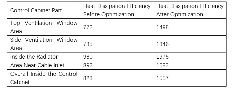
After optimizing the heat dissipation of the offshore wind farm wind turbine box - type transformer control cabinet, the heat dissipation efficiency of different parts of the control cabinet before and after optimization was recorded, as shown in Table 2.
2.3 Results and Discussion
Based on the experimental data in Table 2, the heat dissipation efficiency of the offshore wind turbine pad-mounted transformer control cabinet shows significant improvements after optimization:
3 Conclusion
This study analyzed the impact of the offshore wind farm’s harsh environment on control cabinet heat dissipation. Guided by heat transfer principles, a targeted optimization scheme was proposed and validated experimentally. The optimized design not only improves heat dissipation efficiency and reduces internal temperatures but also enhances corrosion resistance and extends service life. These measures provide robust technical support for the sustainable operation of offshore wind farms.


