In naturally oil-circulated transformers (ONAN/ONAF, etc.), guide plates (also called oil baffles) are widely installed in the windings as a cooling structure primarily to address the issue of oil flow short-circuiting inside the transformer. They force the cooling oil to flow through the horizontal ducts between disc coils, thereby significantly reducing the "hot-spot temperature" of the windings.
The specific reasons and cooling mechanisms are as follows:
1. Addressing "Oil Flow Short-Circuiting" under Natural Convection
In conventional coil structures without guide plates (such as continuous or interleaved disc windings), the cooling oil relies mainly on buoyancy (thermosiphon effect) generated by thermal expansion to rise naturally.
-
Resistance disparity: The vertical oil ducts on both the inner and outer sides of the winding have large cross-sectional areas and thus low fluid resistance, whereas the horizontal ducts between adjacent disc coils are narrow and offer high fluid resistance.
-
Short-circuiting phenomenon: As the cooling oil rises, it naturally tends to follow the path of least resistance—the vertical ducts—effectively bypassing the horizontal passages. As a result, oil flow inside the disc coils (especially deep within the horizontal ducts) becomes extremely slow or even stagnant. Heat cannot be effectively carried away, creating a high risk of dangerous local hot spots.
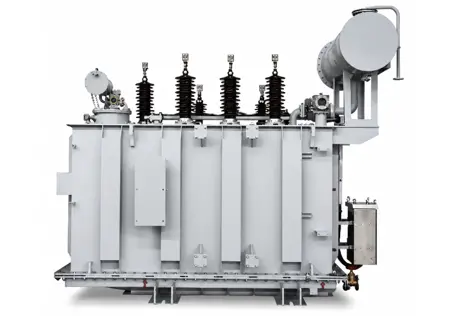
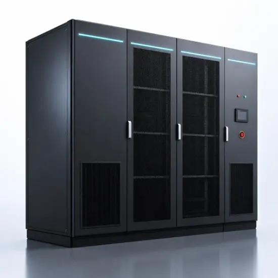
Vziman SZ Series Naturally Oil‑circulated Transformer
2. Forced Flow Diversion by Guide Plates (S‑shaped or Z‑shaped oil flow)
To overcome this inefficient flow regime, insulating baffles (guide plates) are alternately placed in the vertical ducts at regular intervals along the winding height.
-
Altering the flow path: The guide plates block the direct vertical passage, forcing the buoyancy-driven rising oil to change direction. It must flow horizontally through the horizontal ducts between disc coils and then detour into the vertical duct on the opposite side to continue its upward journey.
-
Creating a meandering flow: By alternately arranging guide plates in the inner and outer vertical ducts, the oil is forced into a zigzag "Z"‑shaped or "S"‑shaped path, effectively eliminating flow dead zones.
3. Key Engineering Advantages Gained
-
Significant reduction in hot-spot temperature: Forcing the oil to flow transversely across the coil surfaces swiftly carries away heat from deep within the windings, effectively suppressing local overheating and protecting the life of the insulation paper.
-
Enhanced convective heat transfer coefficient: The guide plates reduce the flow cross‑section, increasing the oil velocity through the horizontal ducts. This strengthens convective heat exchange between the oil and the coil surfaces, improving overall heat dissipation.
-
More uniform temperature distribution: The overall temperature gradient from the bottom to the top of the winding becomes smoother, reducing thermal stress.
-
Increased transformer capacity and service life: Without adding external power (i.e., no oil pumps for forced circulation) or enlarging the transformer size, this internal structural optimization alone significantly improves cooling efficiency, directly enhancing overload capability and insulation lifespan.
Summary: Installing guide plates in naturally oil‑circulated transformers is equivalent to achieving "internal directed flow guidance" within a passive natural‑convection system. This low‑cost, high‑benefit structural improvement has become an indispensable standard feature in the coil cooling design of modern medium‑ and large‑capacity transformers.
Building upon the efficient heat‑dissipation foundation of natural oil circulation with guide plates, the Vziman transformer further incorporates an integrated sealed design (15% volume reduction) and a low‑loss core, achieving a remarkable energy efficiency improvement of over 8% in both no‑load and load losses.
Equipped with a built‑in high‑precision intelligent voltage regulation module (≤±0.5%) and an advanced monitoring system, it ensures high reliability and low‑noise operation (≤55 dB) while significantly reducing long‑term maintenance costs. This product is an ideal choice for power plants, substations, and industrial/mining enterprises seeking both high performance and economic benefits.
Edited From:Echo

 Login
Login