• Product
  • Suppliers
  • Manufacturers
  • Solutions
  • Free tools
  • Knowledges
  • Experts
  • Communities
Search


Life Cycle Cost Analysis of Power Transformers Based on IEC Standards

Edwiin
Edwiin
Field: Power switch
China

Life Cycle Cost Analysis of Power Transformers Based on IEC Standards

Core Framework Under IEC Standards

According to IEC 60300-3-3, the life cycle cost (LCC) of power transformers includes five stages:

  • Initial Investment Costs: Procurement, installation, and commissioning (e.g., 20% of total LCC for a 220kV transformer).

  • Operational Costs: Energy losses (60%-80% of LCC), maintenance, and inspections (e.g., annual savings of 2,600 kWh for a 1250kVA dry-type transformer).

  • Decommissioning Costs: Residual value (5%-20% of initial investment) minus environmental disposal fees.

  • Risk Costs: Outage losses and environmental penalties (calculated as fault frequency × repair time × unit loss cost).

  • Environmental Externalities: Carbon emissions (e.g., 0.96 kg CO₂/kWh loss, totaling tens of thousands over a 40-year lifespan).

Key Cost Optimization Strategies

Efficiency & Material Innovation:

  • PEI Value: IEC TS 60076-20 introduces the Peak Efficiency Index (PEI) to balance no-load/load losses.

  • Aluminum Windings: Reduce costs by 23.5% compared to copper, with improved heat dissipation.

Operational Strategies:

  • Load Rate Optimization: Economic load rates (60%-80%) minimize losses (e.g., 14.3万元 annual savings for a 220kV transformer).

  • Demand-Side Response: Peak shaving reduces LCC by 12.5%.

  • Digital Modeling: Integrate parameters like efficiency curves and failure rates for dynamic cost simulations.

Case Studies

Case 1 (220kV Transformer):

Option A (Standard): Initial cost = 8 million yuan, 40-year LCC = 34.766 million yuan.

Option B (High-Efficiency): Initial cost 10.4% higher, but total LCC reduced by 11.8% due to 4.096 million yuan in energy savings.

Case 2 (400kVA Amorphous Core Transformer):

Reduces carbon-linked LCC (CLCC) by 15.2% but increases failure rates by 20%.

Challenges & Recommendations

  • Data Gaps: Incomplete failure rate statistics may skew models (e.g., 35% of LCC attributed to faults in 10kV transformers).

  • Policy Alignment: Link energy efficiency standards to LCC (e.g., China’s GB 20052-2024 mandates efficiency upgrades).

  • Future Trends: AI-driven decision tools and circular economy designs (e.g., modular structures improve residual value by 5%-10%).
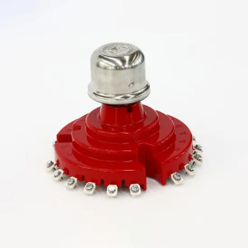
Give a tip and encourage the author!
Recommended
What Are the Handling Procedures After Transformer Gas (Buchholz) Protection Activation?
What Are the Handling Procedures After Transformer Gas (Buchholz) Protection Activation?When the transformer gas (Buchholz) protection device operates, a thorough inspection, careful analysis, and accurate judgment must be carried out immediately, followed by appropriate corrective actions.1. When the Gas Protection Alarm Signal is ActivatedUpon activation of the gas protection alarm, the transformer should be inspected immediately to determine the cause of operation. Check whether it was caused
Felix Spark
11/01/2025
Fluxgate Sensors in SST: Precision & Protection
What is SST?SST stands for Solid-State Transformer, also known as Power Electronic Transformer (PET). From the perspective of power transmission, a typical SST connects to a 10 kV AC grid on the primary side and outputs approximately 800 V DC on the secondary side. The power conversion process generally involves two stages: AC-to-DC and DC-to-DC (step-down). When the output is used for individual equipment or integrated into servers, an additional stage to step down from 800 V to 48 V is require
Echo
11/01/2025
SST Voltage Challenges: Topologies & SiC Tech
One of the core challenges of Solid-State Transformers (SST) is that the voltage rating of a single power semiconductor device is far insufficient to directly handle medium-voltage distribution networks (e.g., 10 kV). Addressing this voltage limitation does not rely on a single technology, but rather a "combination approach." The main strategies can be categorized into two types: "internal" (through device-level technological and material innovation) and "external collaboration" (through circuit
Echo
11/01/2025
SST Revolution: From Data Centers to Grids
Abstract: On October 16, 2025, NVIDIA released the white paper "800 VDC Architecture for Next-Generation AI Infrastructure", highlighting that with the rapid advancement of large AI models and continuous iteration of CPU and GPU technologies, the power per rack has increased from 10 kW in 2020 to 150 kW in 2025, and is projected to reach 1 MW per rack by 2028. For such megawatt-level power loads and extreme power densities, traditional low-voltage AC distribution systems are no longer sufficient
Echo
10/31/2025
Related Products
Send inquiry
Download
Get the IEE Business Application
Use the IEE-Business app to find equipment, obtain solutions, connect with experts, and participate in industry collaboration anytime, anywhere—fully supporting the development of your power projects and business.