How does the winding type affect the generated current and voltages?

How Winding Types (Wave or Lap) Affect Generated Current and Voltage
The type of winding (wave or lap) has a significant impact on the current and voltage generated by motors or transformers. Different winding types exhibit distinct characteristics in terms of magnetic field distribution, current path, inductance, and resistance. Below are the main differences between wave windings and lap windings and their effects on current and voltage:
Wave Winding
Features
Connection Method: In wave windings, the wire alternates in and out of each slot, forming a continuous wavelike path.
Parallel Paths: Typically, there are only two parallel paths, making wave windings suitable for high-voltage, low-current applications.
Magnetic Field Distribution: The magnetic field distribution is relatively uniform because each wire is evenly distributed across the stator slots.
Inductance and Resistance: Due to the longer wire path, the inductance and resistance are relatively high.
Effects
Current: Wave windings are suitable for low-current applications because they have fewer parallel paths, resulting in higher current per path.
Voltage: Wave windings are suitable for high-voltage applications because of their higher inductance, which helps stabilize voltage output.
Efficiency: Due to the higher inductance, wave windings may have lower efficiency at high frequencies.
Lap Winding
Features
Connection Method: In lap windings, the wire is connected sequentially in each slot, forming multiple parallel paths.
Parallel Paths: Typically, there are multiple parallel paths, making lap windings suitable for low-voltage, high-current applications.
Magnetic Field Distribution: The magnetic field distribution is more concentrated because the wires are concentrated in certain areas.
Inductance and Resistance: Due to the shorter wire path, the inductance and resistance are relatively low.
Effects
Current: Lap windings are suitable for high-current applications because they have more parallel paths, resulting in lower current per path.
Voltage: Lap windings are suitable for low-voltage applications because of their lower inductance, which helps increase current output.
Efficiency: Due to the lower inductance, lap windings may have higher efficiency at high frequencies.
Comparison and Selection
Wave Winding vs. Lap Winding
Current and Voltage:
Wave Winding: Suitable for high-voltage, low-current applications, such as DC generators and motors.
Lap Winding: Suitable for low-voltage, high-current applications, such as AC generators and motors.
Magnetic Field Distribution:
Wave Winding: Uniform magnetic field distribution, suitable for applications requiring a uniform magnetic field.
Lap Winding: Concentrated magnetic field distribution, suitable for applications requiring high current density.
Inductance and Resistance:
Wave Winding: Higher inductance and resistance, suitable for applications requiring high inductance.
Lap Winding: Lower inductance and resistance, suitable for applications requiring low inductance.
Summary
When selecting a winding type, consider the following factors:
Application Requirements: Choose the appropriate winding type based on the required current and voltage.
Magnetic Field Distribution: Choose the winding type based on the required magnetic field distribution.
Inductance and Resistance: Choose the winding type based on the required inductance and resistance.
By understanding these characteristics, you can better select and design the winding type for motors or transformers to meet specific application requirements.
Recommended


-
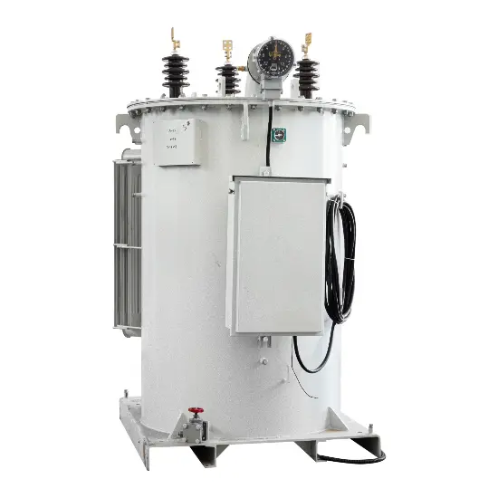
6kV 6.35kV 7.62kV 13.2kV 13.8kV 14.4 kV Overhead Line Single Phase Automatic Step Voltage Regulator
-
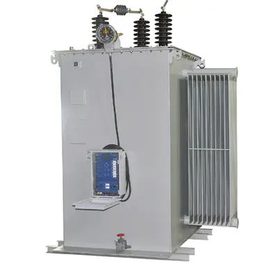
Continuous / Step voltage regulation step voltage regulator 6kV 6.35kV 11kV 15kV 22kV 33kV – IEEE
-
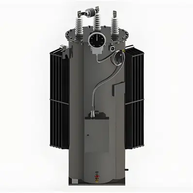
11kV 15kV 22kV 33kV Fully automated, maintenance-free 32 step voltage regulator for distribution lines
-
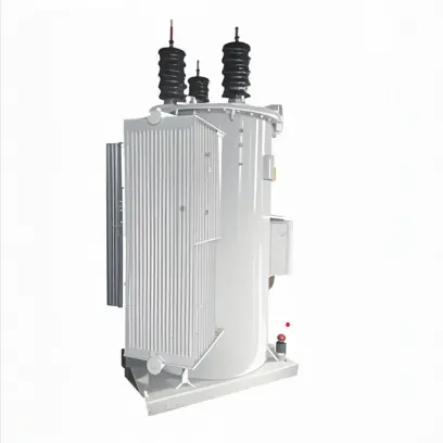
Single Phase Automatic Voltage Regulator – 7.62 kV 13.8 kV 14.4 kV 19.92 kV 34.5 kV IEC 60076 compliant for Power Industry