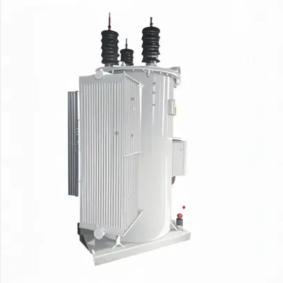
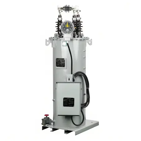
What is the difference between a fixed tap-changer transformer and an on-load tap-changer (OLTC) transformer?

09/30/2024

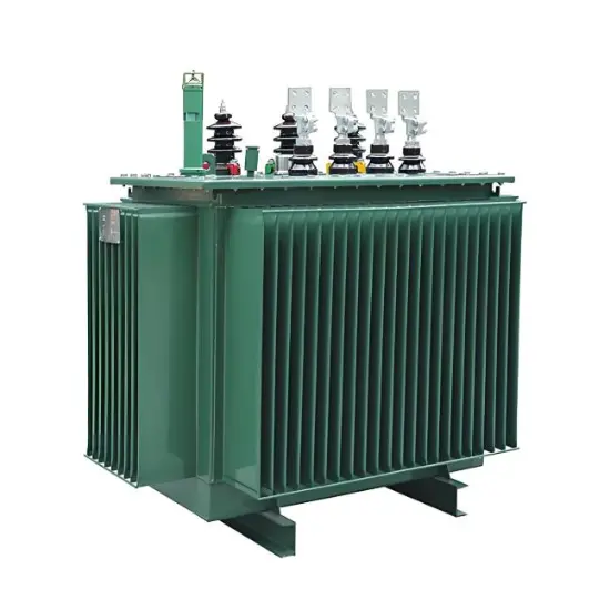
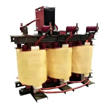
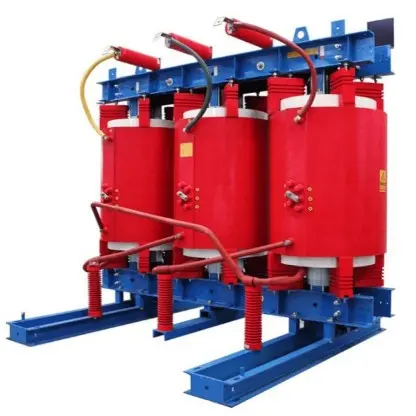
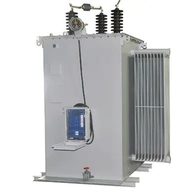
Fixed Tap Changer (Fixed Tap Changer) and On-Load tap changer (OLTC) are both devices used to regulate the output voltage of a Transformer, but they work differently and in different application scenarios. Here are the differences between the two types of transformers:


Fixed Tap Transformer (Fixed Tap Transformer)


Working principle


  • Fixed tap-changer transformers usually have only one or a few pre-set tap-changer positions, which determine the ratio of the transformer.


  • When the transformer ratio needs to be changed, the load must be disconnected, the transformer out of the operating state, manually or through auxiliary equipment to switch to the desired tap position.


  • This switching operation is usually performed in the event of a transformer outage, so it is also known as an Off-Load Tap Changer (OLT).


Peculiarity


  • Lower cost: Compared to on-load tap-changer transformers, fixed tap-changer transformers have a lower cost.


  • Easy maintenance: Due to the low operating frequency, the fixed tap-changer has less wear and is relatively easy to maintain.


  • Application limitation: It is suitable for occasions where the load changes little or does not require frequent voltage regulation.


On-Load Tap Changer (OLTC)


Working principle


  • The on-load tap-changer transformer can adjust the transformer ratio in a live state (that is, the load is not interrupted).


  • Through the internal switching mechanism, it is possible to switch between different tap positions, so as to achieve continuous voltage regulation.


  • This switching operation can be carried out when the transformer is running with power, so it is also known as on-load tap-changer.


Peculiarity


  • Dynamic regulation: It can adjust the voltage in real time according to the actual demand of the power grid to ensure the quality of power supply.


  • Strong adaptability: It is suitable for occasions where the load changes greatly or the voltage needs to be adjusted frequently.


  • Higher cost: Due to technical complexity, the cost of on-load tap-changer is higher than that of fixed tap-changer.


  • Complex maintenance: The on-load tap-changer needs regular maintenance to ensure reliable operation due to its complex internal structure when working in a live state.


Application scenario comparison


Fixed tap-changer transformer


  • Application scenario: Applicable to situations where the load is relatively stable, such as small power distribution stations and rural power grids.


  • Advantages: Low cost, simple maintenance.


  • Disadvantages: inconvenient adjustment, need power outage operation.


On-load tap-changer transformer


  • Application scenario: Applicable to situations where the load changes greatly and the voltage needs to be adjusted frequently, such as urban distribution power stations and large industrial users.


  • Advantages: can dynamically adjust the voltage, improve the quality of power supply.


  • Disadvantages: High cost and complex maintenance.


Sum up


The fixed tap-changer transformer is suitable for situations where the load changes little and the regulation frequency is low, while the on-load tap-changer transformer is suitable for situations where the load changes greatly and the voltage needs to be adjusted in real time. The type of transformer chosen depends on factors such as the specific application requirements, cost budget, and maintenance conditions. Although the on-load tap-changer is expensive and complex to maintain, it has been widely used in modern power systems because of its ability to regulate voltage in a live state.


The Electricity Encyclopedia is dedicated to accelerating the dissemination and application of electricity knowledge and adding impetus to the development and innovation of the electricity industry.

What factors need to be considered when designing a transformer?
Transformer design is a complex process that requires consideration of multiple factors to ensure safe and efficient operation. In addition, compliance with international and local regulations is essential to guarantee that transformers meet safety and performance standards. Below are key factors to consider in transformer design and the relevant regulations to follow:Transformer Design Factors: Voltage and Frequency: Determine the input and output voltage levels and the operating frequency. The
Vziman
09/02/2025
What failure modes are possible in a transformer? How to identify and fix these failures?
Transformers are critical components in power systems, and various failure modes can affect their operation. Timely identification and resolution of these failure modes are essential to prevent costly downtime and ensure system reliability. Below are some common transformer failure modes, along with methods to identify and address them: Insulation FailureIdentification: Insulation failure leads to decreased insulation resistance, which can be detected through insulation resistance testing (megge
09/02/2025
Fault Analysis and Treatment of Oil-Immersed Transformers
Oil Leakage at Welded JointsOil leakage at welded joints primarily stems from poor welding quality, such as incomplete or detached welds, and defects like pinholes and gas pores. Although oil-immersed transformers are initially coated with solder and paint during manufacturing, potentially masking these issues temporarily, the defects tend to surface during operation. Additionally, electromagnetic vibration can cause weld cracks, leading to oil leakage.To resolve such leaks, the first critical s
08/29/2025
Transformer Connection Sections
Transformer Connection DesignationsThe transformer connection designation indicates the winding connection method and the phase relationship between the line voltages of the primary and secondary windings. It consists of two parts: letters and a number. The letters on the left denote the connection configurations of the high-voltage and low-voltage windings, while the number on the right is an integer from 0 to 11.This number represents the phase shift of the low-voltage winding's line voltage r
08/15/2025
Inquiry
Download
IEE-Business is dedicated to serving the personnel in the global power industry.
Join IEE-Business, not only can you discover power equipment and power knowledge, but also canhnd like - minded friends!