Resistance and Leakage Reactance or Impedance of Transformer

Electrical4u
05/07/2024

image.png

Leakage Reactance of Transformer

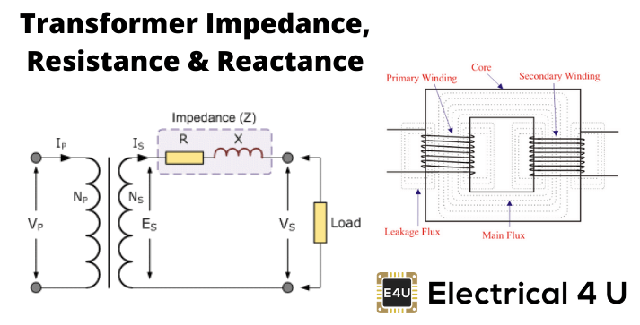
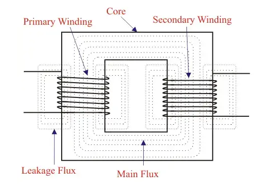
All the flux in transformer will not be able to link with both the primary and secondary windings. A small portion of flux will link either winding but not both. This portion of flux is called leakage flux. Due to this leakage flux in transformer, there will be a self-reactance in the concerned winding.

This self-reactance of transformer is alternatively known as leakage reactance of transformer. This self-reactance associated with resistance of transformer is impedance. Due to this impedance of transformer, there will be voltage drops in both primary and secondary transformer windings.

Resistance of Transformer

Generally, both primary and secondary windings of electrical power transformer are made of copper. Copper is a very good conductor of current but not a super conductor. Actually, super conductor and super conductivity both are conceptual, practically they are not available. So both windings will have some resistance. This internal resistance of both primary and secondary windings is collectively known as resistance of transformer.

Impedance of Transformer

As we said, both primary and secondary windings will have resistance and leakage reactance. These resistance and reactance will be in combination, is nothing but impedance of transformer. If R1 and R2 and X1 and X2 are primary and secondary resistance and leakage reactance of transformer respectively, then Z1 and Z2 impedance of primary and secondary windings are respectively,

image.png

The Impedance of transformer plays a vital role during parallel operation of transformer.

Leakage Flux in Transformer

In ideal transformer, all the flux will link with both primary and secondary windings but in reality, it is impossible to link all the flux in transformer with both primary and secondary windings. Although maximum flux will link with both windings through the core of transformer but still there will be a small amount of flux which will link either winding but not both. This flux is called leakage flux which will pass through the winding insulation and transformer insulating oil instead of passing through core. Due to this leakage flux in transformer, both primary and secondary windings have leakage reactance. The reactance of transformer is nothing but leakage reactance of transformer. This phenomenon in transformer is known as Magnetic leakage.

image.png

Voltage drops in the windings occur due to impedance of transformer. Impedance is combination of resistance and leakage reactance of transformer. If we apply voltage V1 across primary of transformer, there will be a component I1X1 to balance primary self induced emf due to primary leakage reactance. (Here, X1 is primary leakage reactance). Now if we also consider voltage drop due to primary resistance of transformer, then voltage equation of a transformer can easily be written as,

image.png

Similarly for secondary leakage reactance, the voltage equation of secondary side is,

image.png

Here in the figure above, the primary and secondary windings are shown in separate limbs, and this arrangement could result in a large leakage flux in transformer because there is a big room for leakage. Leakage in primary and secondary windings could be eliminated if the windings could be made to occupy the same space. This, of course, is physically impossible but, by placing secondary and primary in a concentric manner can solve the problem to a good extent.


Statement: Respect the original, good articles worth sharing, if there is infringement please contact delete.

Electrical4u

Electrical4U is dedicated to the teaching and sharing of all things related to electrical and electronics engineering.

What are the differences between an alternating current generator and a direct current generator?
Main Differences Between AC and DC GeneratorsAn electrical machine is a device that converts mechanical energy into electrical energy and vice versa. A generator is a type of such machine that converts mechanical energy into electrical energy. However, the electrical energy generated can be in either alternating current (AC) or direct current (DC) form. Thus, the primary difference between AC and DC generators is that they generate alternating current and direct current respectively. While there
Edwiin
07/18/2025
What are the common faults of low-voltage voltage transformers?
Open - Circuit Fault on the Secondary SideOpen - circuit in the secondary side is a typical fault of low - voltage voltage transformers, showing abnormal voltmeter readings (zero/fluctuation), faulty power meters, buzzing noises, and core overheating. When open - circuited, the secondary voltage spikes (no secondary current to balance the primary EMF), causing core saturation, flux distortion, and potential overheating/damage.Causes include loose terminals, poor contact, or human error. In low
Felix Spark
07/18/2025
Analysis of Transformer Capacity, Load Rate and Number of Units Selection Issues
The safe and economical operation of power transformers is related to the safety, economy, stability, and reliability of the operations of various industries. The limitations of conditions such as the investment economic indicators for its selection, the economic benefits of maintenance and operation, and the adaptability in the new environment (access of distributed power sources, configuration of energy storage, etc.) make it impossible to include comprehensive factors in other aspects.The cap
Leon
07/17/2025
Analysis of the Impact of Immersion on the Performance of Low-Voltage Current Transformers
1 IntroductionLow - voltage current transformers for metering, with a through - core type epoxy resin structure, are widely used in distribution transformer areas and for small - to - medium - sized industrial and commercial electricity consumption. As a range expander for electric energy metering, their performance directly relates to electricity consumption safety and the accuracy of users' trade calculations. Studying long - term immersion's impact on these transformers is practically signifi
Felix Spark
07/17/2025
Inquiry
Download
IEE-Business is dedicated to serving the personnel in the global power industry.
Join IEE-Business, not only can you discover power equipment and power knowledge, but also canhnd like - minded friends!