• Product
  • Suppliers
  • Manufacturers
  • Solutions
  • Free tools
  • Knowledges
  • Experts
  • Communities
Search


Electrical Slip Ring: What is it?

Electrical4u
Electrical4u
Field: Basic Electrical
0
China

{041F785D-2705-4c35-A446-64A55308738F}.png

What is a Slip Ring?

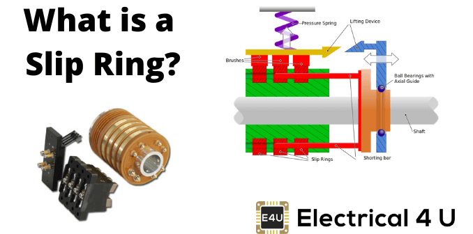
A slip ring is defined as an electromechanical device that is used to connect a stationary system to a rotating system. It is used in applications that require rotation while transmitting power or electrical signals.

The slip ring also is known as an electrical rotary joint, rotating electrical connector, or electrical swivels. It is used in various electrical machines to improve mechanical performance and simplify the operation.

If a device rotating for a fixed number of revolutions. It may be possible to use a power cable with sufficient length. But it is a quite complex setup. And it is impossible if components rotate continuously. This setup is not practical and reliable for this type of application.

How does a Slip Ring work?

The slip rings consist of two main components; metal ring and brush contact. According to the application and design of the machine, the number of rings and brushes are decided.

The brushes are made up of graphite or phosphor bronze. The graphite is an economical option but the phosphor bronze has good conductivity and more wear life.


Depending on the RPM (rotations per minute), the brushes are fixed with rotating rings, or rings are rotating with fixed brushes. In both of these arrangements, the brushes maintain contact with the ring by pressure from the springs.

Generally, rings are mounted on the rotor and it is rotating. And brushes are fixed and mounted on the brush house.

The rings are made up of conductive metal like brass and silver. It is mounted shaft but insulated with a center shaft. The rings are insulated from each other by nylon or plastic.

As the rings rotate, the electrical current is conducted through the brushes. Therefore, it makes a continuous connection between the rings (rotating system) and brushes (fixed system).

Slip ring vs Commutator

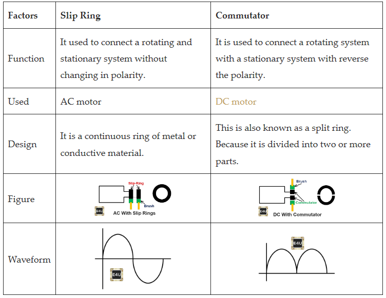
The slip ring and commutator both are used to maintain a connection between the rotating system and the electrical system. But the function of both of these arrangements is different. Both the slip ring and commutator made of conductive material.

In the below table, we summarized differences between the slip ring and commutator.

image.png

Types of Slip Rings

Slip rings are classified into various types according to construction and size. Types of slip rings are explained as below.

Pancake Slip Ring

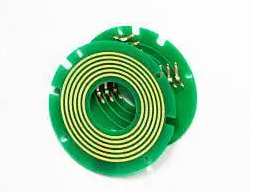
In this type of slip ring, the conductors are arranged on a flat disc. This type of concentric disc placed on the center of a rotating shaft. The shape of this slip is flat. So, it is also known as a flat slip ring or platter slip ring.

It will reduce axial length. Therefore, this type of slip ring is designed for space-critical applications. This arrangement has more weight and volume. It has greater capacitance and greater brush wear.

{6000248C-B369-4470-A75F-9A6B1D5FC864}.png

Pancake Slip Ring

Mercury Contact Slip Ring

In this type of slip ring, mercury contact is used as a conducting media. Under the normal temperature condition, it can transfer current and electrical signals by liquid metal.

The mercury contact slip ring features strong stability and less noise. And it provides the most scientific and economical option for applications in industries.

But the use of mercury creates a safety concern. Because it is a toxic substance. It is very dangerous to use this type of slip ring in applications like food manufacturing or processing and pharmaceutical. This is because it may corrupt the product if there is a mercury leakage.

{A7CEF9BB-14DE-4754-A261-1B98BCDA4B0E}.png

Mercury Contact Slip Ring


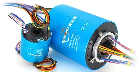
Through Hole Slip Rings

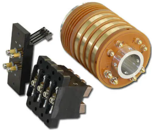
This type of slip ring has a hole in the center of the slip ring. It is used in devices where requires to transmit power or signal when need 360˚ rotating.

This type of slip rings is designed to install with a flange on a sleeve bracket. It has free space in the center for connecting the shaft of a machine without affecting cable while it is rotating.


It has a long life span and offers low noise and maintenance. This type of slip ring is used for routing hydraulic pneumatic passages and it can integrate with high-frequency joints.

{34DD86A8-9578-4d27-91D0-3EE718D34BF8}.png

Through Hole Slip Rings


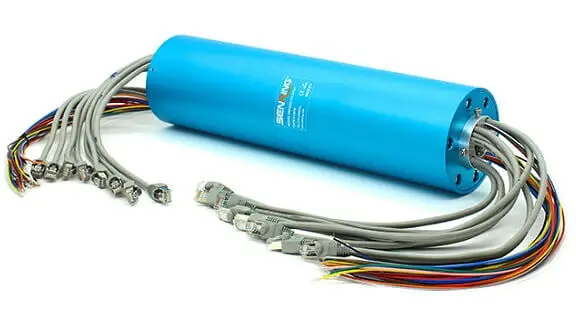
Ethernet Slip Ring

This type of slip ring is developed to provide reliable products that allow the transfer of the ethernet protocol through a rotary system.

While choosing an ethernet slip ring for communication, there are three important parameters that must be considered; Return Loss, Insertion Loss, and Crosstalk.

Ethernet slip rings designed to meet the requirement of matching impedance, reducing losses, and controlling crosstalk.

{E5337D06-BB4E-4307-90EF-C687DE58FCCA}.png

Ethernet Slip Ring


Miniature Slip Rings

This type of slip ring is very small in size and it is designed for small devices to transfer signals or power from a rotating device.

Miniature slip rings are ideal for electrical devices like control panel, video transmitter, and sensor.

{6708BA8D-397A-4bc0-BE77-796619C00565}.png


Miniature Slip Rings


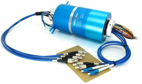
Fiber Optic Slip Ring

This type of slip ring is designed to pass signals across rotating interfaces when a large amount of data needs to transfer.

Fiber optic slip ring is also known as the Fiber Optic joint or Fiber-Electric Rotary joint. This type of slip ring is used in the application like; sensor signal management, HD video transmission system, radar, and video monitoring system, medical equipment, microwave communication, etc.

{7F7870C7-558C-410b-9172-20A29EE701AD}.png


Fiber Optic Slip Ring


Wireless Slip Ring

This type of slip ring is not using carbon brushes or friction-based metal rings. As the name suggests, it can transfer data and power wirelessly. For that, it uses the electromagnetic field.

The electromagnetic field produced by the coils which are placed in the rotating receiver and stationary transmitter.

The wireless slip ring is the best alternative for the traditional slip ring as it reduced the mechanical contacts. Therefore, it can be used in harsh environments and it reduces maintenance.

But the only disadvantages are that the power that can be transmitted between the coil is limited. For the same volume of traditional slip ring can transfer more amount of power compared to the wireless slip ring.

{D94A1EED-F535-418c-8A7F-ECAA1DA83A66}.png

Wireless Slip Ring

Statement: Respect the original, good articles worth sharing, if there is infringement please contact delete.


Give a tip and encourage the author!
Recommended
SST Technology: Full-Scenario Analysis in Power Generation, Transmission, Distribution, and Consumption
I. Research BackgroundPower System Transformation NeedsChanges in energy structure are placing higher demands on power systems. Traditional power systems are transitioning toward new-generation power systems, with the core differences between them outlined as follows: Dimension Traditional Power System New-Type Power System Technical Foundation Form Mechanical Electromagnetic System Dominated by Synchronous Machines and Power Electronic Equipment Generation-Side Form M
Echo
10/28/2025
Understanding Rectifier and Power Transformer Variations
Differences Between Rectifier Transformers and Power TransformersRectifier transformers and power transformers both belong to the transformer family, but they differ fundamentally in application and functional characteristics. The transformers commonly seen on utility poles are typically power transformers, while those supplying electrolytic cells or electroplating equipment in factories are usually rectifier transformers. Understanding their differences requires examining three aspects: working
Echo
10/27/2025
SST Transformer Core Loss Calculation and Winding Optimization Guide
SST High-Frequency Isolated Transformer Core Design and Calculation Material Characteristics Impact:Core material exhibits varying loss behavior under different temperatures, frequencies, and flux densities. These characteristics form the foundation of overall core loss and require precise understanding of nonlinear properties. Stray Magnetic Field Interference:High-frequency stray magnetic fields around windings can induce additional core losses. If not properly managed, these parasitic losses
Dyson
10/27/2025
Upgrade Traditional Transformers: Amorphous or Solid-State?
I. Core Innovation: A Dual Revolution in Materials and StructureTwo key innovations:Material Innovation: Amorphous AlloyWhat it is: A metallic material formed by ultra-rapid solidification, featuring a disordered, non-crystalline atomic structure.Key Advantage: Extremely low core loss (no-load loss), which is 60%–80% lower than that of traditional silicon steel transformers.Why it matters: No-load loss occurs continuously, 24/7, throughout a transformer’s lifecycle. For transformers with low loa
Echo
10/27/2025
Send inquiry
Download
Get the IEE Business Application
Use the IEE-Business app to find equipment, obtain solutions, connect with experts, and participate in industry collaboration anytime, anywhere—fully supporting the development of your power projects and business.