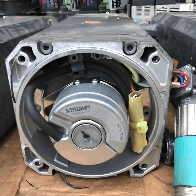
Winding of rectangular armature coils

11/25/2024

Winding Methods for Rectangular Armature Coils

The winding method for rectangular armature coils depends on specific application and design requirements. There are typically two main methods:

1. Layer Winding (Single-Layer Winding)

In this method, the wire is wound layer by layer along the edges of the rectangular core, with each turn closely packed against the previous turn, forming one or multiple layers. This method is suitable for applications requiring high-density windings and limited space.

Features:

  • Uniform Distribution: Each turn of wire is evenly distributed along the edges of the rectangular core, ensuring a uniform magnetic field distribution.

  • Compact Structure: Multiple layers can achieve a high coil density, making it suitable for high-power applications.

  • Insulation Handling: Insulation is required between layers to prevent short circuits.

2. Helical Winding (Spiral Winding)

In this method, the wire is wound in a spiral pattern along the edges of the rectangular core, forming a helical structure. This method is suitable for applications requiring longer wire paths or specific magnetic field distributions.

Features:

  • Helical Structure: The wire is arranged in a spiral pattern along the edges of the rectangular core.

  • Magnetic Field Distribution: Helical winding can produce specific magnetic field distributions, suitable for certain specialized applications.

  • Space Utilization: Helical winding can better utilize space, making it suitable for cores with special shapes.

Selection Criteria

Layer Winding Applicability:

  • High-Density Windings: Suitable for applications requiring high-density windings in limited space.

  • Uniform Magnetic Field: Required for ensuring a uniform magnetic field distribution.

  • Multi-Layer Structure: Needed for increasing inductance or current-carrying capacity with multiple layers.

Helical Winding Applicability:

  • Special Magnetic Field Distributions: Required for producing specific magnetic field distributions.

  • Long Wire Paths: Needed for increasing resistance or inductance with longer wire paths.

  • Special Shapes: Suitable for cores with irregular or special shapes.

Examples

Layer Winding Example

  • Prepare the Core: Fix the rectangular core on a stable workbench.

  • Starting Point: Secure the starting end of the wire at one corner of the core.

  • Winding: Wind the wire layer by layer along the edges of the rectangular core, ensuring each turn is tightly packed.

  • Insulation Handling: Place insulation material between layers to prevent short circuits.

  • Ending Point: After completing the winding, secure the ending end of the wire on the core.

Helical Winding Example

  • Prepare the Core: Fix the rectangular core on a stable workbench.

  • Starting Point: Secure the starting end of the wire at one corner of the core.

  • Winding: Wind the wire in a spiral pattern along the edges of the rectangular core, forming a helical structure.

  • Insulation Handling: Place insulation material where necessary to prevent short circuits.

  • Ending Point: After completing the winding, secure the ending end of the wire on the core.

Summary

When choosing a winding method, consider the specific application requirements and design criteria. Layer winding is suitable for applications requiring high-density windings and uniform magnetic field distribution, while helical winding is suitable for applications requiring specific magnetic field distributions or longer wire paths.

Hello,I'm Wdwiin. A decade of hands-on experience in electrical engineering, specializing in high-voltage systems, smart grids, and renewable energy technologies. Passionate about technical exchange and knowledge sharing, committed to interpreting industry trends with professional insights to empower peers. Connection creates value—let’s explore the boundless possibilities of the electrical world together!

Ensuring Reliability: A Deep Dive into Transformer Maintenance
IntroductionElectric transformers are the backbone of modern power distribution systems, silently enabling the reliable delivery of electricity to homes, businesses, and industries. As these critical assets age and the demand for uninterrupted power grows, the importance of diligent transformer maintenance has never been greater. This essay explores the essential role of transformer maintenance, highlighting the value of proactive care, the impact of advanced diagnostic technologies, and the tra
Vziman
09/03/2025
What factors need to be considered when designing a transformer?
Transformer design is a complex process that requires consideration of multiple factors to ensure safe and efficient operation. In addition, compliance with international and local regulations is essential to guarantee that transformers meet safety and performance standards. Below are key factors to consider in transformer design and the relevant regulations to follow:Transformer Design Factors: Voltage and Frequency: Determine the input and output voltage levels and the operating frequency. The
Vziman
09/02/2025
What failure modes are possible in a transformer? How to identify and fix these failures?
Transformers are critical components in power systems, and various failure modes can affect their operation. Timely identification and resolution of these failure modes are essential to prevent costly downtime and ensure system reliability. Below are some common transformer failure modes, along with methods to identify and address them: Insulation FailureIdentification: Insulation failure leads to decreased insulation resistance, which can be detected through insulation resistance testing (megge
09/02/2025
Fault Analysis and Treatment of Oil-Immersed Transformers
Oil Leakage at Welded JointsOil leakage at welded joints primarily stems from poor welding quality, such as incomplete or detached welds, and defects like pinholes and gas pores. Although oil-immersed transformers are initially coated with solder and paint during manufacturing, potentially masking these issues temporarily, the defects tend to surface during operation. Additionally, electromagnetic vibration can cause weld cracks, leading to oil leakage.To resolve such leaks, the first critical s
08/29/2025
Inquiry
Download
IEE-Business is dedicated to serving the personnel in the global power industry.
Join IEE-Business, not only can you discover power equipment and power knowledge, but also canhnd like - minded friends!