• Product
  • Suppliers
  • Manufacturers
  • Solutions
  • Free tools
  • Knowledges
  • Experts
  • Communities
Search


Disconnector Switches Grouping in HVDC Grids

Edwiin
Edwiin
Field: Power switch
China

HVDC disconnector switches:
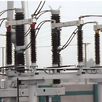
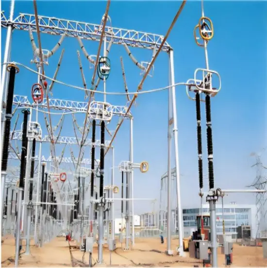
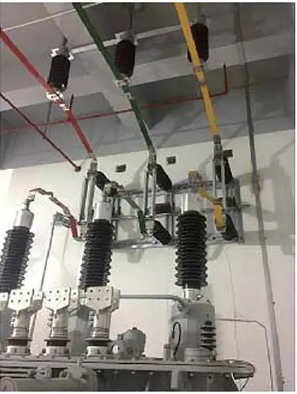
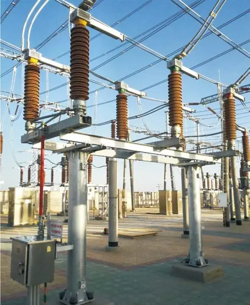
HVDC disconnecting switches (DS) are used to disconnect various circuits in HVDC transmission networks. For example, the HVDC DS is applied to switching duties such as line or cable-charging current switching, no-load line, or cable transfer switching, in addition to disconnecting equipment including a converter bank (thyristor valve), a filter bank, and a grounding line. HVDC DS is also applied to DC switchgear to terminate the residual or leakage current through an interrupter after clearing a fault current.

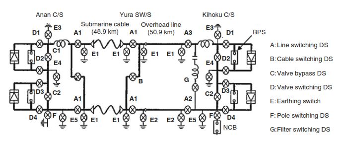
Example of a single pole diagram of HVDC disconnecting switch

Figure 1: Example of a single-pole diagram of HVDC disconnecting switch in bipolar HVDC system

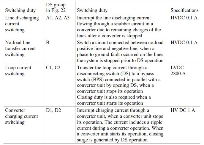
Figure 1 shows an example of a single-pole diagram with related switching equipment (except for the Metallic return transfer breaker) in the bipolar HVDC transmission system in Japan. In general, the requirements for HVDC DS and ES in the HVDC system are similar to the HVAC DS and ES used in the AC system, but some equipment includes additional requirements depending on their application. Table 1 gives major switching duties imposed on these HVDC DS (CIGRE JWG A3/B4.34 2017).

Main switching duties of disconnecting switch (DS) applied to bipolar HVDC system

Table 1: Main switching duties of disconnecting switch (DS) applied to the bipolar HVDC system

HVDC disconnector switch groups:
Group A: The DS is required to interrupt the line discharging current due to residual charges of a submarine cable which has a relatively large capacitance (approximately 20 μF). The residual voltage induced in the line after a converter halt is discharged through a snubber circuit in a converter bank at both C/Ss (Anan C/S and Kihoku C/S) to the ground. The discharge time constant is about 40 s, which corresponds to a discharging time of 3 min. The discharge current was set to 0.1 A based on the value calculated from the residual voltage of 125 kV and the resistance of the snubber circuit in the thyristor valve.

Group B: The DS is normally used to switch a faulted transmission line to a healthy neutral line in order to use the neutral line for a transmission line temporarily or permanently after the system is completely stopped. This requires the same specifications as the group A DS.

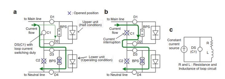
Group C: The DS is required to transfer the nominal load current from the DS to the bypass switch (BPS) connected in parallel with a converter bank in order to restart the bank unit. The specification of the transfer current is 2800 A in this project. Figure 2 illustrates a nominal current transfer process from the DS to the BPS.

At the first, the upper converter bank unit is stopped and the lower converter bank unit is operated. In order to operate the upper bank unit from a halted condition, the DS C1 is opened next to commutate the nominal current into the BPS. Based on the analysis with an equivalent circuit of the current transfer process shown in Fig. 2 c, the requirements for the group C DS are given by the voltage of DC 1 V at a nominal current of 2800 A, where the voltage was calculated with the resistance and inductance per unit length corresponding to the current transfer length including DC-GIS.

Current transfer DS operation of group C

Figure 2: Current transfer DS operation of group C. (a) DS close position, (b) DS open position, (c) equivalent circuit of DS

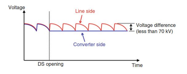
Group D: The DS is required to interrupt a converter bank charging current when a converter bank unit is stopped. Even if the thyristor valve is halted, a ripple current flows through the stray capacitance of the converter bank. The analytical result shows that it is highly probable that the ripple current is chopped less than 1 A, and the recovery voltage due to the difference between the residual DC voltage of the converter side and the DC voltage of the line side which includes ripple components is less than 70 kV as shown in Fig 3.

Voltage difference between DS contacts

Figure 3: Voltage difference between DS contacts

Conclusion about HVDC disconnector switch grouping:
The switching performance of all HVDC DSs of groups A to D was designed based on the AC DS, and its performance was confirmed by factory tests with the testing conditions shown in Table 1 There are no significant design differences between HVAC DS and HVDC DS except for the creepage distance, which is about 20% longer for HVDC applications.

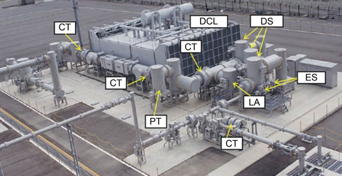
DC-DS&ES, DC-CT&VT, DC-MOSA (LA) used for 500 kV-DC GIS

Figure 4: DC-DS&ES, DC-CT&VT, DC-MOSA (LA) used for 500 kV-DC GIS

Gas-insulated switchgear (DC-GIS) composed of several HVDC DS and earthing switches (ES) is also applied in HVDC networks close to a coastline. Figure 4 shows an example of DC-GIS including DC DS and DC ES that were installed at the converter station in the bipolar HVDC system, which was commissioned in 2000.

Give a tip and encourage the author!
Topics:
Recommended
How Does Oil Loss Affect SF6 Relay Performance?
1.SF6 Electrical Equipment and the Common Problem of Oil Leakage in SF6 Density RelaysSF6 electrical equipment is now widely used in power utilities and industrial enterprises, significantly advancing the development of the power industry. The arc-quenching and insulating medium in such equipment is sulfur hexafluoride (SF6) gas, which must not leak. Any leakage compromises the reliable and safe operation of the equipment, making it essential to monitor the SF6 gas density. Currently, mechanical
Felix Spark
10/21/2025
MVDC: Future of Efficient, Sustainable Power Grids
The Global Energy Landscape Is Undergoing a Fundamental Transformation toward a "fully electrified society," characterized by widespread carbon-neutral energy and the electrification of industry, transportation, and residential loads.In today’s context of high copper prices, critical mineral conflicts, and congested AC power grids, Medium-Voltage Direct Current (MVDC) systems can overcome many limitations of traditional AC networks. MVDC significantly enhances transmission capacity and efficienc
Edwiin
10/21/2025
Grounding Causes of Cable Lines and the Principles of Incident Handling
Our 220 kV substation is located far from the urban center in a remote area, surrounded primarily by industrial zones such as Lanshan, Hebin, and Tasha Industrial Parks. Major high-load consumers in these zones—including silicon carbide, ferroalloy, and calcium carbide plants—account for approximately 83.87% of our bureau’s total load. The substation operates at voltage levels of 220 kV, 110 kV, and 35 kV.The 35 kV low-voltage side mainly supplies feeders to ferroalloy and silicon carbide plants
Felix Spark
10/21/2025
Overhead Power Lines & Towers: Types, Design & Safety
Besides ultra-high voltage AC substations, what we encounter more frequently are power transmission and distribution lines. Tall towers carry conductors that leap across mountains and seas, stretching into the distance before reaching cities and villages. This is also an interesting topic—today, let's explore transmission lines and their supporting towers.Power Transmission and DistributionFirst, let’s understand how electricity is delivered. The electric power industry primarily consists of fou
Encyclopedia
10/21/2025
Related Products
Send inquiry
Download
Get the IEE Business Application
Use the IEE-Business app to find equipment, obtain solutions, connect with experts, and participate in industry collaboration anytime, anywhere—fully supporting the development of your power projects and business.