1. Pêşnûna Testkirina Destpêka Kablê ya Bihêrkirî
Testkirina destpêka kablê ya bihêrkirî dike wekî pêwistîna xebitandî yên elektrîkî yên çend hêmanên rastî yên taybetî yên serbest, induksiyon, kapasitan û veyanî, bîngav bikar bînin da ku ji bo bistîna kablê an dawî hatine girîkar kirin. Mîna yekemîn û mînakîn testekirin da ku parmetreyên rastî yên jînî yên kablê digire, bingehîn da ku amadeyên parmetreyên rastî yên jînî yên kablê bide ku li ser hesabkirina baranî yên sistemê ya elektrîkî, agahdarî yên releya îndikasyon, analîzê ya xebitandîya qetme û nirxandina avastiyê ya karbikêrî.
Nirxekî nîvîstî yekemîn û duêmîn da ku: yekemîn, nirxekirina ferzaneya nîvîstî yên dizayn û pêdivî yên herînandin, bingehîn da ku wereqetandinên parmetreyê wereqetandinên sisteman de wereqetandinên parmetreyê wereqetandinên parmetreyê wereqetandinên parmetreyê; duêmîn, destpêka "databaza parmetreyên bîngav" bikin bibe ku bîngav bike bibe ku bîngav bike bibe ku bîngav bike bibe (misalî, kevseriya bîngav û bingehîn da ku lînkên bîngav). Li ser DL/T 596 "Regulasyonên Testkirina Pirvektîva Cihazên Elektrîkî" û GB 50217 "Standartên Dizaynê ya Kableyan ên Elektrîkî," hemî testekirinan destpêka hewldebixweyî yên 220 kV û lê zêdeyan dawî hatine girîkar kirin, herwa 110 kV û lê bihêr hatine girîkar kirin li ser ehemmiyeti sisteman.
2. Prosesa Tamîn Testkirina Destpêka Kablê ya Bihêrkirî
2.1 Faseya Têyara Testkirina Berderê
2.1.1 Berhevkirina Agahdarî Teknik û Serchiliş
Hemî parmetreyên dizaynê ya kablê ya berderê hewce ye ku werin girtin, bîngehîn da ku sathîya bihêrkirî (misalî, 220 kV, 500 kV), modelê ya kablê (misalî, YJV22-220 kV-1×2500 mm²), rêbazê ya destnus (berderandina direk, kanal, tray), derêjê (têketin 0.1 km), materyalê ya konduktor (mes û alûminî), tipê ya kevser (XLPE, papîrên bekeyf), struktûra metallic shield (belîk û tel) û rêbazê ya grounding (berderandina direk, cross-bonded grounding). Serchiliş hewce ye ku bivekare komunikasyon di navenda testkirina serokî (misalî, istasyona terminala kablê) û navenda yârdest (istasyona substation), integritiyê ya sistemê ya grounding, derêjêya nîvîstî yên cihanî yên energî (≥1.5 her çendî sathîya nîvîstî yên testkirina bihêrkirî) û electrostatic voltmeter bikar bînin bibe ku bivekare voltage induced (ku dikare di kablên near energized lines de hêsanîya desetan volt, hewce ye ku bivekare şertên anti-electrocution).
2.1.2 Rewşbûna Planê ya Testkirina û Hilbijêrekan Cihaz
Li ser "Guidelines for Cable Line Parameter Testing," planê ya detalî bikar bînin bibe ku bivekare test items (positive-sequence resistance, zero-sequence capacitance, etc.), modelsên cihaz, rêbazê ya wiring û tedbîrên nîvîstî. Cihazên core:
Line parameter tester (accuracy class 0.2, frequency range 45–65 Hz, output current ≥10 A);
Three-phase voltage regulator (capacity ≥5 kVA, adjustable range 0–400 V);
Isolation transformer (1:1 ratio to prevent grid interference);
Auxiliary tools: thermometer/hygrometer (ambient temperature and humidity must be recorded for temperature correction of parameters), discharge rod (25 kV class, discharge time ≥5 min), shorting wires (cross-sectional area ≥25 mm² copper cable, length customized on-site), and insulating pole (3 m, insulation resistance ≥1000 MΩ).
2.1.3 Tedbîrên Nîvîstî
Navenda testkirina hewce ye ku bivekare barriers û signs "High Voltage Danger." Navenda serokî û yârdest hewce ye ku bivekare walkie-talkies (communication range ≥1 km) û emergency stop buttons. Hemî personelê ya testkirina hewce ye ku bivekare gloves û shoes (breakdown voltage ≥15 kV) û safety harnesses. Enda dawî kablê hewce ye ku bivekare disconnected from other equipment û bivekare temporary grounding wires bingehîn da ku wereqetandinên back-feeding.
2.2 Faseya Testkirina Berderê
2.2.1 Wiring û Phase Verification
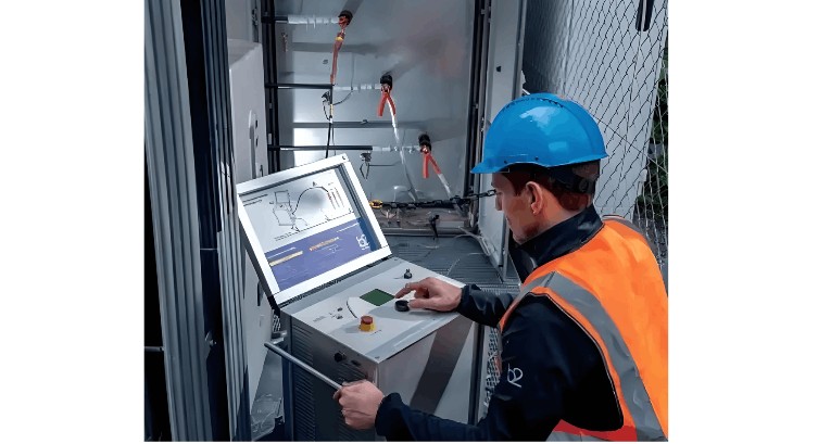
Misalî, positive-sequence parameter testing, wiring procedure:(1) Short-circuit and ground the three-phase conductors (A, B, C) at the far end; ground the metallic shield at one end only (for cross-bonded systems, disconnect the bonding links in the cross-bonding box and test each section separately);
(2) Apply AC voltage (typically 380 V) to phase A at the main test end via a voltage regulator and isolation transformer; leave phases B and C open; connect the voltage and current sampling leads of the line parameter tester.
Phase verification: Use a multimeter to measure the voltage phase of each phase to ensure correct same-name phase connections and avoid measurement errors due to incorrect phase sequence.
2.2.2 Procedureya Measurement Parameter
Positive-sequence resistance (R1) and reactance (X1): Apply test current (typically 5–10 A) to phase A, measure the magnitude and phase angle difference between voltage and current, and calculate using the formulas R1 = U/I·cosϕ and X1 = U/I·sinϕ. Repeat the test three times and take the average value, with at least a 1-minute interval between tests to prevent conductor heating from affecting resistance values.
Zero-sequence capacitance (C0): Short-circuit and connect phases A, B, and C to the high-voltage terminal of the tester, ground the metallic shield, apply 100 V, and measure capacitance using the Schering bridge principle. Linearity must be verified at different voltage levels (50 V, 100 V, 200 V), with deviations ≤2%.
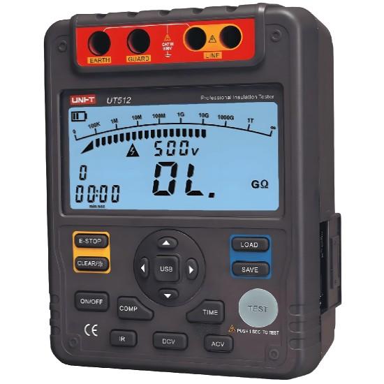
Insulation resistance (Rins): Use a 2500 V megohmmeter to measure insulation resistance between conductor and shield. Record the reading after 1 minute of applied voltage and simultaneously record ambient temperature. Convert to the 20°C reference value using the formula R20 = Rt × 10^(0.004(t−20)) (where t is the measured temperature).
2.2.3 Data Recording and Validity Assessment
Immediately after completing each parameter test, record the instrument reading, ambient temperature and humidity, test time, and any anomalies (e.g., voltage fluctuations, unusual noises). Data validity criteria include:
Relative deviation of three repeated measurements of the same parameter ≤5%;
Deviation of positive-sequence impedance from design value ≤10% (accounting for installation length error);
Insulation resistance, after temperature correction, should be ≥1000 MΩ·km (standard for XLPE cables).
2.3 Faseya Post-Test Processing
2.3.1 Safe Discharge and Wiring Removal
After testing, first disconnect the power supply to the voltage regulator. Then, use a discharge rod to perform "multiple discharges" on the cable conductor and shield (each discharge lasting ≥1 minute, with a 30-second interval). Only after confirming the residual voltage is ≤50 V should the shorting wires and test leads be removed. For cross-bonded systems, reconnect the bonding links in the cross-bonding box and measure continuity to ensure proper connection.
2.3.2 Data Correction and Report Preparation
According to GB/T 3048.4 "Methods for Electrical Testing of Electric Wires and Cables," measured parameters must be corrected for temperature and frequency:
Resistance temperature correction:
For copper conductors: R₂₀ = Rₜ / [1 + α(t − 20)] (where α = 0.00393/°C);
Capacitance frequency correction:
When the test frequency deviates from 50 Hz, correct using: C₅₀ = Cf × (1 + 0.002∣f − 50∣).
The test report must include the testing standard (e.g., DL/T 475), instrument calibration certificate number, a parameter comparison table (design values vs. measured values), and a conclusive assessment (e.g., "Pass", "Retest Recommended").