What is the difference between a grounding transformer and an arc suppression coil?

Overview of Grounding Transformers
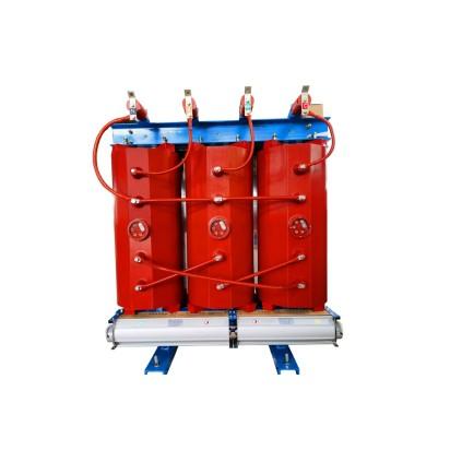
A grounding transformer, commonly referred to as a "grounding transformer" or simply "grounding unit," can be classified into oil-immersed and dry-type based on the insulating medium, and into three-phase and single-phase based on the number of phases. The primary function of a grounding transformer is to provide an artificial neutral point for power systems whose transformers or generators lack a natural neutral (e.g., delta-connected systems). This artificial neutral enables the use of either a peterson coil (arc suppression coil) or a low-resistance grounding method, thereby reducing the capacitive ground-fault current during single-line-to-ground faults and enhancing the reliability of the distribution system.
Overview of Arc Suppression Coils (Peterson Coils)
As the name suggests, an arc suppression coil is designed to extinguish arcs. It is an iron-core inductive coil connected between the neutral point of a transformer (or generator) and earth, forming an arc-suppression-coil grounding system. This configuration represents one type of small-current grounding system. Under normal operating conditions, no current flows through the coil. However, when the grid is struck by lightning or experiences a single-phase arcing ground fault, the neutral-point voltage rises to phase voltage. At this moment, the inductive current from the arc suppression coil counteracts the capacitive fault current, effectively compensating it. The resulting residual current becomes very small—insufficient to sustain the arc—allowing it to extinguish naturally. This rapidly eliminates the ground fault without triggering dangerous overvoltages.

The key role of the arc suppression coil is to supply inductive current that compensates for the capacitive current at the fault point during a single-phase ground fault, reducing the total fault current to below 10 A. This helps prevent arc re-ignition after current zero-crossing, achieves arc extinction, reduces the likelihood of high-magnitude overvoltages, and prevents fault escalation. When properly tuned, the arc suppression coil not only minimizes the probability of arc-induced overvoltages but also suppresses their amplitude and reduces thermal damage at the fault point and voltage rise on the grounding grid.
Proper tuning means the inductive current (IL) matches or closely approximates the capacitive current (IC). In engineering practice, the degree of detuning is expressed by the detuning factor V:

When V=0, it is called full compensation (resonant condition).
When V>0, it is under-compensation.
When V<0, it is over-compensation.
Ideally, for optimal arc suppression, the absolute value of V should be as small as possible—preferably zero (full compensation). However, under normal grid operation, a small detuning (especially full compensation) can lead to series resonance overvoltages. For example, in a 6 kV coal mine power system, the neutral-point displacement voltage under full compensation can be 10 to 25 times higher than in an ungrounded system—commonly known as series resonance overvoltage. Additionally, switching operations (e.g., energizing large motors or non-synchronous circuit breaker closure) may also induce hazardous overvoltages. Therefore, when no ground fault exists, operating the arc suppression coil near resonance poses a risk rather than a safety benefit. In practice, arc suppression coils operating in or near full compensation are typically equipped with a damping resistor to suppress resonance overvoltages, and field experience has shown this approach to be highly effective.
Difference Between Grounding Transformers and Arc Suppression Coils
In China’s 10 kV three-phase power distribution systems, the neutral point is typically ungrounded. To prevent intermittent capacitive currents during single-phase ground faults from causing sustained arcing and voltage oscillations—which could escalate into major incidents—a grounding transformer is used to create an artificial neutral point. The grounding transformer usually employs a zigzag (Z-type) winding connection. Its neutral point is connected to an arc suppression coil, which is then grounded. During a single-phase ground fault, the inductive current from the arc suppression coil cancels out the system’s capacitive current, allowing the system to continue operating for up to 2 hours while maintenance personnel locate and clear the fault.
Thus, the grounding transformer and the arc suppression coil are two distinct devices: the arc suppression coil is essentially a large inductor, connected between the neutral point provided by the grounding transformer and earth. They work together as a coordinated system—but serve fundamentally different functions.


-
Customization 66kV 88kV 110kV 132kV Three Phase Z-type winding Oil-Immersed Earthing Transformer source manufacturer

-
15kV 20kV 22kV 30kV 33kV 35kV oil-immersed neutral grounding resistance to transformer (earthing transfoemer)

-
35kV 36kV 44kV 66kV Three Phase Cast Resin Dry Type Zigzag (Z-Type) Grounding Transformer

-
Customization 15kV 30kV 33kV 34.5kV 36kV Three Phase Neutral Grounding/earthing Transformer direct supply


