What Are the Steps for Error Testing GIS Voltage Transformers?

Hey everyone, I'm Oliver, and I've been working with current transformers (CTs) and voltage transformers (VTs) for 8 years.
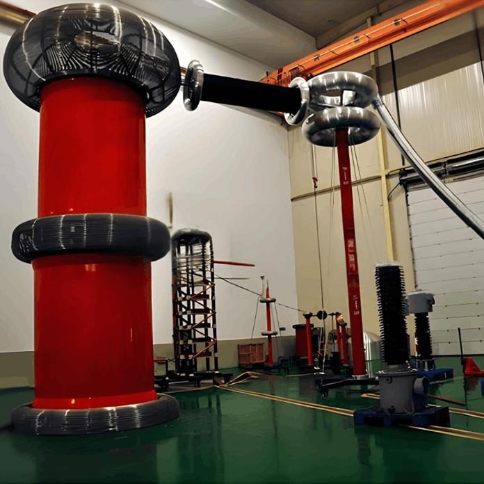
From assisting my mentor on site to leading high-voltage testing teams and conducting error calibrations independently, I’ve dealt with all kinds of instrument transformers — especially those used in GIS systems. The error test for voltage transformers is something I perform regularly.
A few days ago, a friend asked me:
“Oliver, how exactly do you perform an error test on a GIS voltage transformer? What’s the process?”
That’s a super practical question! So today, I want to share with you:
What are the actual steps involved in testing the error of a GIS voltage transformer — and what should you watch out for?
No complicated jargon — just plain, real-world talk based on my hands-on experience over the past eight years. Let’s get into it!
1. What Is a VT Error Test?
Simply put, an error test checks whether the output voltage of the VT matches the actual input voltage — in other words, how accurate the transformer really is.
If the error is too large:
The metering data will be off, which affects billing.
Protection devices might misinterpret signals and either trip unnecessarily or fail to operate when needed.
So this isn’t just a formality — it’s a critical check.
2. Preparation Before the Test
2.1 Clarify the Purpose
Are you testing for factory acceptance, commissioning, or routine maintenance? Each case may have slightly different requirements.
2.2 Check Connections and Safety
Ensure the primary side of the VT is de-energized and properly grounded.
Confirm secondary wiring is correct.
Make sure your test equipment — like the voltage booster, standard VT, and error tester — is in good condition and within calibration period.
2.3 Prepare Reference Equipment
You’ll usually need a high-accuracy reference voltage transformer to compare against the one being tested.
2.4 Step-by-Step Testing Procedure
Step 1: Set Up the Test Circuit
Connect the primary side to the voltage source.
Connect both the test VT and the standard VT in parallel.
Connect the secondary outputs to the error tester.
Important: Make sure the polarity is correct — otherwise, errors will be exaggerated or the test will fail outright.
Step 2: Slowly Raise the Voltage to Rated Level
Increase voltage gradually and evenly.
Watch for any unusual sounds or signs of discharge.
Once rated voltage is reached, let it stabilize for a moment.
Step 3: Record the Error Data
At rated voltage, read and record:
Ratio error
Phase angle error
Also test under different load conditions — such as 25%, 50%, and 100% of rated burden.
Step 4: Analyze the Results
Compare the measured values with national standards or nameplate specifications.
If the error exceeds acceptable limits, the VT may need further inspection or repair.
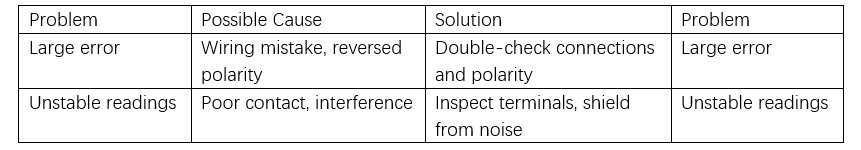
3. Common Issues & How to Handle Them
4. Final Thoughts
As someone who's worked in this field for 8 years, here's what I’ve learned:
“The VT error test may seem detailed, but as long as the procedure is followed carefully and the setup is solid, it’s totally manageable.”
If you're new, try doing it with an experienced colleague at least once. And if you're seasoned, don’t get complacent — safety and accuracy always come first.If you ever run into issues during testing or feel unsure about certain steps, feel free to reach out. I’m happy to share more hands-on experience and tips.Here’s hoping every GIS voltage transformer runs safely and accurately!
— Oliver