
High-voltage disconnect switches (or fuses) do not have arc-extinguishing capability, but they provide a clearly visible break point. Therefore, they are used solely as isolation components in a circuit. They are installed at the beginning of a circuit or in front of components requiring maintenance. When a circuit needs to be de-energized for maintenance, the power is first interrupted using a switching device, and then the disconnect switch is opened. This ensures a clearly visible break in the circuit, guaranteeing personnel safety.
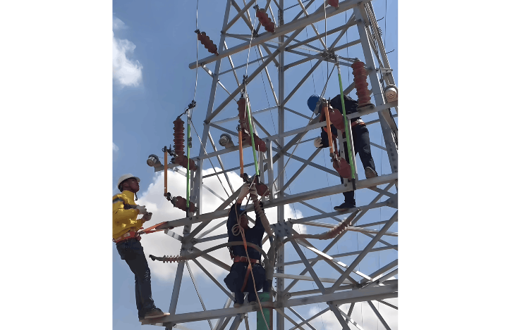
When operating an expulsion type disconnect switch, personnel must use an insulating rod rated for the appropriate voltage level and which has passed required testing. They must wear insulated shoes, insulated gloves, an insulated helmet, and protective goggles, or stand on a dry wooden platform. Another person must supervise the operation to ensure personnel safety.
Sequence for transformer power-down and power-up operations: During power-down, first disconnect the low-voltage load side, then sequentially de-energize from low-voltage to high-voltage. Specifically: disconnect all low-voltage loads first, then open the indoor high-voltage load switch, followed by the outdoor circuit breaker, and finally open the outdoor high-voltage expulsion type disconnect switch. This sequence avoids interrupting large currents through the switches, thereby reducing the magnitude and frequency of switching overvoltages.
Generally, it is strictly prohibited to operate an expulsion type disconnect switch under load. If a disconnect switch is accidentally closed under load, even if it was a mistake, it must not be re-opened. However, if a disconnect switch is mistakenly opened under load, when the moving contact just begins to separate from the fixed contact and an arc appears, the switch should immediately be closed again to extinguish the arc and prevent the incident from escalating. But if the disconnect switch has already been opened more than 30%, it is not permitted to re-close the mistakenly opened switch.
When de-energizing or energizing, operators must avoid any impact at the beginning or end of the operation of the expulsion type disconnect switch. Impact can easily damage the switch’s moving contacts. The force application when closing an expulsion type disconnect switch follows the pattern: slow (initial movement) → fast (as the moving contact approaches the stationary contact) → slow (as the moving contact nears the final closing position). The force application when opening follows: slow (initial movement) → fast (as the moving contact approaches the stationary contact) → slow (as the moving contact nears the final opening position). The fast movement is intended to quickly extinguish the arc and prevent equipment short circuits and contact burn damage; the slow movement is intended to prevent mechanical damage to the fuse caused by operational impact forces.
Sequence for operating the three phases of a high-voltage expulsion type disconnect switch:
For power-down: First open the middle phase, then open the two side phases.
For power-up: First close the two side phases, then close the middle phase.
The reason for opening the middle phase first during power-down is primarily because the current interrupted in the middle phase is smaller than that in the side phases (as part of the load is shared by the remaining two phases), resulting in a smaller arc and posing no danger to the other phases. When operating the second phase (a side phase), the current is larger, but since the middle phase is already open, the two remaining fuses are spaced farther apart, preventing the arc from lengthening and causing a phase-to-phase short circuit. In windy conditions, power-down operations should follow this sequence: first open the middle phase, then the downwind phase, and finally the upwind phase. For power-up, the sequence is: first close the upwind phase, then the downwind phase, and finally the middle phase. This procedure helps prevent wind-blown arcs from causing short circuits.


