
1 Sersanîna Teknolojîya Pirastkirina Baranê (FCL)
Rêzikên pirastkirina baranê pasif tradisyonel—wisa bikarhêneriyan lêgerên dihêran, reaktoran sertî, an operasyonên bisetên xwar—da ku ji bo hêsanên bingehên din, taybetmendiyên din an jêrîn de çêkirin, zêdetirina împedansa sistemê ya destpêk, an kêm kirina amana û stabilitê yên sistema. Yekemîn yekemîn ên rêzikên vê tûr dibe ku ji bo roja rastên elektrikê ya rast û mezin nekar bêne.
Di her duve, teknolojîyên pirastkirina baranê aktîf, bi nîşanî Pirastkirina Baranê (FCLs), da ku ji bo operasyon normala roja rastan împedansê ya bicêt e. Wanê ku serokdarî biguherîne, FCL çêt bike derbas dar împedansê ya bilind e, wekheviya ku baranê pirast bike, bi tenê ku kontrol dinamîkî ye. FCLs ji ber teknolojiyên piştguhên, wisa elektronika guhantir, superkonduktivitî, û kontrola girdêkê hatine şanasandin.
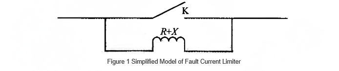
Prinsîpê asayî ya FCL li gorî modelê ya nîşan kirîn da: ji bo operasyon normaleya sistema, switch K pêk bike, û FCL heç tiplimîn împedansê ya pirastkirina baranê nehatîne. Tenha wanê ku serokdarî biguherîne, K çêt bike, û reaktorê têk bike ku baranê pirast bike.
Zêdeyî FCLs li ser modela asayî ya vê ya vê taybetmendî û variantên pêşketinê hatine şanasandin. Têkilîyên sereka di navbera FCLên jêrîn de li ser natûra împedansa pirastkirina baranê, implementasyona switch K, û strategiyên kontrolê.
2 Şemas û Statusa Barkirina FCL
2.1 Pirastkirina Baranê Superkonduktiv (SFCLs)
SFCLs bi rêzikên quench-type an non-quench-type hatine nirxandin li ser ema bikarhênerin transitasyonê ya superkonduktorê ji statê superkonduktiv bi statê normal (S/N) ji bo pirastkirina baranê. Li ser struktura, wan dikarin wek resistive, bridge-type, magnetically shielded, transformer-type, an saturated-core types nirxandin. SFCLs bi rêzikên quench-type depandîn li transitasyonê ya S/N (triggered wanê ku derece, girdêka magnetîk, an baran ji bo navberên kritîk hatine kevirin), ku superkonduktor digire ji împedansê sifirî ji bo împedansê ya bilind, bi tenê ku baranê pirast bike.
SFCLs bi rêzikên non-quench-type superkonduktor coils bi komponentên din (wisa elektronika guhantir an elementên magnetîk) hatine birbirvêrînin û kontrol bike modên operasyonî ji bo pirastkirina baranê ya serdast. Barkirina praktîkî ya SFCLs bi çend rêzikên superkonduktivî, wisa maliyet û efektivîyeya serdkerdina serkeftin, hêsan dibe. Ji ber virê, dema sererastkirina uzmeyan SFCLs bi rêzikên quench-type dema sererastkirina uzmeyan dirêj e, ku dikare bi sererastkirina sistema werîne, wanê ku SFCLs bi rêzikên non-quench-type changes împedansa dikare afet bidin ser koordinasyonê ya relay protection, ku hewceyê reset bikin.
2.2 Pirastkirina Baranê Element Magnetîk
Wan dikarin wek flux-cancellation type an magnetic saturation switch type nirxandin. Di flux-cancellation type de, du windings bi polârîtên têkildîn hatine têkildin ser core yekem. Bi operasyon normaleya, fluxên bermecelan û tepceran di navberan de cancel bikin, ku împedansa lekêşîn ên bicêt e.
Bi serokdarî, yek winding bypass bike, balanca fluxê biguheze, û împedansa bilind têk bike. Cûreya magnetic saturation switch type operasyon bike bi biasing current-limiting winding into saturation (bi DC bias, etc.) bi operasyon normale, ku împedansa bicêt e. Bi serokdarî, baranê serdast core ji saturation biguheze, û împedansa bilind têk bike ji bo pirastkirina baranê. Li gorî cihazên kontrolê, limiters element magnetîk barkirina têk dibe.
2.3 PTC Resistor Current Limiters
Resistors Positive Temperature Coefficient (PTC) niha ne û bi operasyon normaleya împedansa bicêt e. Bi serokdarî, temperature wê çêt bike, û împedansa bi 8-10 orders of magnitude within milliseconds çêt bike. FCLs bi PTC resistors barkirina komersîyalkiye li ser projeyên pilot ên voltajê ya bicêt e.
Lêkê, rêzikên din dikarin: overvoltages ên bicêt e li ser inductive current limiting (ku hewceyê parallel overvoltage protection); stres mekanîkî bi tevahî resistor; ratings ên voltaj/baran (hundreds of volts, a few amps), ku hewceyê series-parallel connections û high-voltage use; û dema sererastkirina uzmeyan (several minutes) bi service life ên bicêt e, ku large-scale deployment werin.
2.4 Pirastkirina Baranê Solid-State (SSCLs)
SSCLs niha cîhekên nû yên pirastkirina baranê bi elektronika guhantir, taybetmendî topologies, fast response, high operational endurance, û kontrola sade. Bi kontrol bike state ya cîhêlekên elektronika guhantir, equivalent impedance ya SSCL çêt bike ji bo pirastkirina baranê. Wek FACTS device nû, SSCLs hêzan dibe. Lêkê, bi serokdarî, cîhêlekên elektronika guhantir hewceyê full fault current, ku hewceyê performansa û kapasitya cîhêlekê bikin. Koordinasyon bi multiple SSCLs an bi systems ên kontrol FACTS din dikare çareseribike.
2.5 Pirastkirina Baranê Economical
Wan teknolojiya piştguh, amana, maliyetê bicêt, û switching automatic bejkêrkariya ji bo kontrolê. Wan dikarin wek arc-current transfer an series-resonant types nirxandin. Cûreya arc-current transfer type vacuum switch bi current-limiting resistor têk bike. Bi operasyon normale, load current flows through the switch. Bi serokdarî, switch opens, forcing current to transfer to the resistor for current limiting.
Li gorî cihazên auxiliary, transfer current affected by vacuum arc voltage and stray inductance; transfer time dependent on switch speed; and difficulty in current transfer at low arc voltages, requiring auxiliary devices to boost arc voltage and force current zero-crossing. Series-resonant FCLs use saturated reactors or surge arresters as switches. Under normal conditions, the capacitor and inductor are in series resonance with low impedance. During a fault, high current saturates the reactor or activates the arrester, detuning the resonance and inserting the reactor into the line for current limiting. Electromagnetic repulsion fast switches can also rapidly bypass the capacitor.
2.6 Statusa Engineering Applications ya FCL
Ji bo value praktîkî, FCLs hewceyê not only rapidly insert impedance during faults but also feature automatic reset, multiple consecutive operations, low harmonic generation, and acceptable investment and operating costs. Currently, limited by technical challenges and cost-effectiveness, despite various experimental prototypes developed worldwide, actual grid applications remain scarce, mostly limited to low-voltage, small-capacity pilot projects.
The field started earlier abroad, with notable progress in solid-state and superconducting FCL commercialization. In 1993, a 6.6 MW solid-state breaker using anti-parallel GTOs was installed on a 4.6 kV feeder at the Army Power Center in New Jersey, USA, capable of clearing faults within 300 μs. In 1995, a 13.8 kV/675 A solid-state FCL by EPRI and Westinghouse was commissioned at a PSE&G substation. For superconducting FCLs, a hybrid AC/DC FCL was developed by ACEC-Transport and GEC-Alsthom in 1998, achieving commercialization. In 1999, a 15 kV/1200 A SFCL jointly developed by General Atomics and others was deployed at a Southern California Edison (SCE) substation.
Domestic FCL research started later but progressed rapidly. In 2007, China's 35 kV superconducting saturated-core FCL, developed by Tianjin Electromechanical Holdings and Beijing YunDian YingNa Superconductor Cable Co., Ltd., underwent grid-connected trial operation at Puji Substation, Yunnan—then the world's highest-voltage, highest-capacity superconducting limiter in trial operation. For series-resonant FCLs, China's first 500 kV device, jointly developed by China Electric Power Research Institute, Zhongdian Puri, and East China Grid, was commissioned at the 500 kV Bingyao Station in late 2009, reducing short-circuit current to below 47 kA.
Globally, FCL applications are still limited to individual projects but are gaining increasing attention. Significant potential remains in research on increasing capacity, voltage withstand, material improvements, heat dissipation, cost control, and topology optimization.
3 Impact of FCL Integration on Power System Security and Stability
The rapid impedance insertion of FCLs during faults, while effectively limiting current, alters network parameters, affecting transient stability, voltage stability, relay protection settings, and reclosing. Poor control may lead to negative effects. Coordinated control and optimal configuration are essential for multiple FCLs to achieve optimal performance.
3.1 Impact on Relay Protection and Reclosing Settings
For saturated-core SFCLs, the long recovery time means significant impedance persists post-fault, potentially requiring re-setting of automatic reclosing and relay protection. Literature suggests installing quench-type SFCLs on generator and main transformer branches; although protection re-setting is needed, the persistent high impedance during recovery can act as a braking resistor, benefiting transient stability. Various distance protection setting methods accounting for SFCLs have been proposed. Solid-state FCLs can use thyristor trigger signals, bypass breaker contacts, FCL switch positions, and GAP circuits to switch zero-sequence current protection settings, addressing sensitivity issues after FCL insertion.
3.2 Impact on Transient Power-Angle Stability
While FCLs generally operate with low impedance normally and high impedance during faults, their specific operation and structure lead to varying impacts on transient power-angle stability. Solid-state and superconducting FCLs, by inserting high impedance during faults, can enhance generator electromagnetic power output and improve transient stability.
Resistive-type FCLs improve stability more than inductive types by providing damping resistance that consumes more generator power. However, improper resistance values may cause reverse power flow to the generator, worsening power deficits. Analysis shows that for faults away from the generator, inductive SFCLs become more beneficial as total transfer reactance decreases. Resistive SFCLs also show similar characteristics beyond a threshold resistance.
The impact depends on fault location and type; FCLs affect power-angle stability only when faults occur on their installed lines. For asymmetrical faults at the line start, FCL inductance benefits stability, increasing with inductance value. At the line end, if the fault is cleared quickly, FCL inductance may hinder stability, but the negative impact decreases with higher inductance for phase-to-phase and two-phase-to-ground faults. For single-phase or phase-to-phase faults near the line end, slightly extending fault clearing time makes small FCL inductance beneficial, significantly reducing swing curve amplitude compared to fast clearing.
3.3 Impact on Transient Voltage Stability
Short-circuit faults cause voltage dips, affecting equipment operation and causing economic losses. PSCAD-based analysis shows that larger FCL inductance improves voltage dip suppression within a certain range. The inherent ability of FCLs to improve fault voltage varies with network structure. On radial feeders, FCL reactance >0.5 pu can maintain voltage above 0.8 pu during faults. Local generation or reactive support near the fault bus reduces dependency on FCLs.
3.4 Coordination with Traditional Limiting Measures
Coordinating FCLs with traditional measures (e.g., reactors, high-impedance transformers) is key to practical application. An automatic optimization method using 0–1 variables for measure deployment and integer variables for capacity forms a mixed-integer programming problem, solvable by branch-and-bound methods, to guide coordinated configuration.
3.5 Optimization of Configuration
With multiple FCLs, optimizing location, number, and parameters for cost-effective performance is a research hotspot. For small grids, enumeration or methods based on power change/loss rate suffice. For large grids with multiple nodes exceeding short-circuit limits, enumeration becomes computationally intensive and inadequate for multi-objective problems (impedance, number, location).
Weighted multi-objective optimization using genetic or particle swarm algorithms is common, but results heavily depend on weight selection. Sensitivity-based methods, calculating short-circuit current changes relative to branch impedance, avoid weight dependence and help determine optimal FCL placement, number, and impedance. Since the primary goal is current limiting, optimization can focus on limiting effectiveness, ensuring selected FCL locations affect all nodes with insufficient short-circuit margin. Cost and operational losses are also critical factors in real-world optimization.
4 Development and Application Trends of FCLs
4.1 FCL Technology Research Trends
To leverage advantages and mitigate weaknesses, new research directions are emerging. Combining superconducting FCLs with energy storage is a hot topic—absorbing energy during faults and supplying it to improve power quality during normal operation, achieving dual benefits. The key lies in power conditioning system design.
To address high capacity demands, cost, and harmonics in solid-state limiters, improved topologies like transformer-coupled three-phase bridge SSCLs with bypass inductors have been proposed. Conventional FCLs lack dynamic adjustability and steady-state compensation.
A multi-functional FCL with dynamic series compensation has been proposed: normal operation uses capacitor bank switching for stepwise line compensation; during faults, GTOs or IGCTs control the limiting degree via a series inductor, enabling multi-purpose use. Series compensation must be chosen carefully to avoid sub-synchronous oscillations.
4.2 FCL Application Trends
FCLs not only limit short-circuit currents but, under suitable conditions, can enhance power-angle and voltage stability, expanding their application scope. Emerging trends include improving DC receiving-end transmission capacity, reducing commutation failure risk, enhancing power quality, and supporting large-scale renewable integration.
In multi-terminal DC systems, FCLs can limit current without affecting normal operation. For DC receiving-end grids, FCLs installed on fault propagation paths can isolate regions, block fault propagation, shorten commutation failure duration, accelerate DC power recovery, and mitigate power imbalances and power flow transfers from simultaneous multi-infeed DC failures, enhancing overall transient stability. For large asynchronous motors, integrating SFCLs in the stator circuit enables soft starting and suppresses fault current contribution, reducing voltage dips and improving transient voltage stability.
For large-scale wind integration, FCLs at wind farm connection points can improve fault ride-through capability and reduce disconnection risks. Resistive FCLs require less impedance than inductive types for stability under the same fault duration, but inductive types offer better improvement near critical stability.
As FCL technology matures, these fast-responding, multi-functional devices—limiting faults, enhancing stability, and isolating faults—will find broader applications.
5 Conclusion
FCLs effectively limit short-circuit currents but may impact power-angle/voltage stability, relay protection, and reclosing settings. Optimized configuration and coordinated control of multiple FCLs or with FACTS devices promise significant benefits. Future FCLs will extend beyond current limiting to enhancing DC transmission, reducing commutation failures, improving power quality, and supporting renewable integration.
However, technical and economic barriers delay large-scale application of high-voltage, high-capacity FCLs. Solid-state limiters, limited by device capacity and voltage ratings, are currently restricted to distribution networks. Advances in high-power self-commutating devices may overcome these bottlenecks and reduce costs.
Superconducting FCLs offer fast response and self-triggering but face high cooling costs, heat dissipation challenges, and long quench recovery times. Considering near-term feasibility and economics, economical FCLs based on conventional equipment are the preferred solution. Solid-state limiters, with lower technical barriers and maturity, represent the mainstream future direction.


