Transformer Bushing Operating Principle

Edwiin
08/07/2025

In electrical power systems, a bushing is an insulating device that allows an electrical conductor to pass safely through a grounded conductive barrier, as in the case of transformers or circuit breakers. All transformer windings are connected to high-voltage lines, so special attention must be paid to the terminal connections to prevent flashover between the high-voltage terminals and the transformer body. In low-voltage distribution transformers, cable connections are made within a terminal box on the secondary side.

However, in power transformers, both sides operate at high voltage, necessitating specially designed devices known as bushings. A bushing typically consists of a central current-carrying conductor (a rod, busbar, or cable) and a porcelain housing mounted in the opening of the transformer cover, which insulates the live part. The simplest type is a molded high-quality glazed porcelain insulator with a central conductor. This type is used for voltages up to 33 kV and features a smooth or slightly ribbed surface for indoor applications.

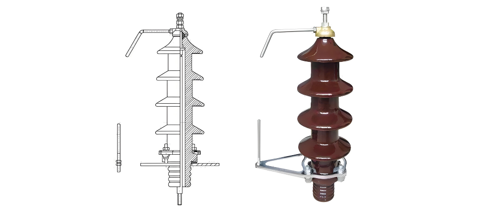
For outdoor transformers, the external (upper) part of the bushing includes sheds to protect the lower ribs from water during rain. For transformers operating above 36 kV, oil-filled or capacitor-type bushings are used. An oil-filled bushing consists of a hollow, two-part porcelain cylinder with a conductor passing through its axis. The space between the conductor and the inner surface of the porcelain is filled with oil, which is separate from the oil in the transformer tank. The top of the bushing connects to a small expansion chamber to accommodate volume changes due to oil temperature variations. Provision is made at the lower end for current transformers, allowing the bushing to be removed without disturbing the current transformer.

A capacitor bushing is constructed with layers of synthetic resin-bonded paper interleaved with thin metallic foils impregnated with conductive material. This forms a series of capacitors, where each pair of metal foils and the intervening resin-bonded paper cylinder acts as a capacitor. By varying the length of the metallic foils and the thickness of the resin-bonded paper layers, the dielectric stress is evenly distributed across the radial depth—i.e., along the radius of the bushing.

Edwiin

Hello,I'm Wdwiin. A decade of hands-on experience in electrical engineering, specializing in high-voltage systems, smart grids, and renewable energy technologies. Passionate about technical exchange and knowledge sharing, committed to interpreting industry trends with professional insights to empower peers. Connection creates value—let’s explore the boundless possibilities of the electrical world together!

Main Transformer Knowledge
Main TransformerThe main transformer is primarily responsible for converting the high-voltage electrical energy generated at power plants into lower-voltage electrical energy suitable for transmission, distribution, and end-use. This process involves stepping down voltage from high to low levels.Working PrincipleThe main transformer operates based on the principles of electromagnetic induction and voltage transformation. When an alternating current (AC) is applied to the high-voltage winding, it
Rockwell
08/07/2025
Working Principle and Introduction of Rectifier Transformers
Working Principle of Rectifier TransformersThe working principle of a rectifier transformer is the same as that of a conventional transformer. A transformer is a device that converts AC voltage based on the principle of electromagnetic induction. Typically, a transformer consists of two electrically isolated windings—the primary and secondary—wound around a common iron core. When the primary winding is connected to an AC power source, the alternating current generates a magnetomotive
Ron
08/07/2025
Common Faults and Diagnostic Technologies of Oil-immersed Distribution Transformers
1.Common Faults and Diagnostic Measures1.1 Transformer Oil Leakage1.1.1 Oil Leakage from Tank Weld SeamsFor oil leakage at flat joints, direct welding is applicable. For leakage at corners or joints reinforced with stiffeners, the exact leakage point is often difficult to locate, and re-leakage may occur after welding due to internal stress. For such cases, repair welding with an added iron plate is recommended: for two-surface joints, the iron plate can be cut into a spindle shape for welding;
Vziman
08/07/2025
Development of SG-Type Open Ventilated Dry Transformers (OVTD)
Prior to the 1960s, dry-type transformers primarily employed Class B insulation in open-ventilated designs, with the product model designated as SG. At that time, foil windings were not yet available, so low-voltage coils were typically constructed using multi-strand conductors in layered or spiral configurations, while high-voltage coils adopted a disc-type design. The conductors used were either double glass-fiber-wrapped wires or single glass-fiber-wrapped wires with alkyd enamel coating.Most
Vziman
08/06/2025
Inquiry
Download
IEE-Business is dedicated to serving the personnel in the global power industry.
Join IEE-Business, not only can you discover power equipment and power knowledge, but also canhnd like - minded friends!