Location of Shunt Capacitors

Shunt Capacitors Definition
Shunt capacitors are devices installed in electrical systems to improve power factor by compensating for reactive power.
Distribution System Capacitor Bank
In distribution feeder capacitor bank are installed on pole to compensate reactive power of that particular feeder. These banks are normally mounted on one of the poles on which the distribution feeders run. The mounted capacitor banks are normally interconnected with over head feeder conductors by means of insulated power cable.
The size of the cable depends upon the voltage rating of the system. The voltage range of the system for which pole mounted capacitor bank can be install, may be from 440 V to 33 KV. The rating of capacitor bank may be from 300 KVAR to MVAR. The pole mounted capacitor bank can be either fixed unit or switched unit depending upon varying load condition.
EHV Shunt Capacitor
In extra high voltage system, the generated electrical power may have to be transmitted a long distance via transmission line. During journey of power, sufficient voltage may be dropped due to inductive effect of the line conductors. This voltage drop may be compensated by providing ∑ HV capacitor bank at ∑ HV sub-station. This drop of voltage is maximum at peak load condition, hence, the capacitor bank installed for in this case should have switching control to make it off and on as when required.
Substation Capacitor Bank
When high inductive load has to be delivered from a high voltage or medium voltage substation, one or more capacitor bank of suitable size should be installed at substation to compensate inductive VAR of the entire load. These capacitors banks are controlled by circuit breaker and provided with lightening arrestors. Typical protection scheme along with protection relays are also provided.
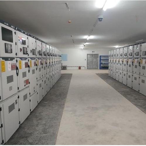
Metal Encoder Capacitor Bank
For small and industrial subtraction indoor type capacitor banks may also be used. These capacitor bank are installed in metal cabinet. This design is compact and bank requires less maintenance. The uses of these banks are more compared to outdoor bank, as these are not exposed to external environment.
Distribution Capacitor Bank
Distribution capacitor banks are normally pole mounted capacitor bank installed nearer to load point or installed at distribution subtraction.
These banks do not help to improve power factor of primary system. These capacitors bank are cheaper than other power capacitors bank. All types of protection schemes for capacitor bank cannot be provided to a pole mounted capacitor bank. Although pole mounted cap bank is outdoor type but sometimes it is kept in metal enclosure to protect from outdoor environmental conditions.
Fixed Capacitor Bank
Some loads, especially industrial ones, need constant reactive power for power factor correction. Fixed capacitor banks, used in such cases, do not have control systems to switch on or off. They operate with the feeders, staying connected as long as the feeders are live.
Switched Capacitor Banks
In high voltage power system, compensation of reactive power is mainly required during peak load condition of system. There may be reverse effect if the bank is connected to the system at mean load condition. At low load condition, the capacitive effect of bank may increase the reactive power of the system instead of decreasing it.
In this situation capacitors bank must be switched ON during peak load poor power factor condition and must also be switched OFF during low load and high power factor condition. Here switched capacitor banks are used. When a capacitor bank is switched ON it provides more or less constant reactive power to the system. It helps to maintain desired power factor of the system even at peak load condition. It prevents, over voltage of system during low load condition as capacitor is disconnected from the system during low load condition. During operation of bank, it reduces losses both of the feeders and transformer of the system as it is directly installed at primary power system.