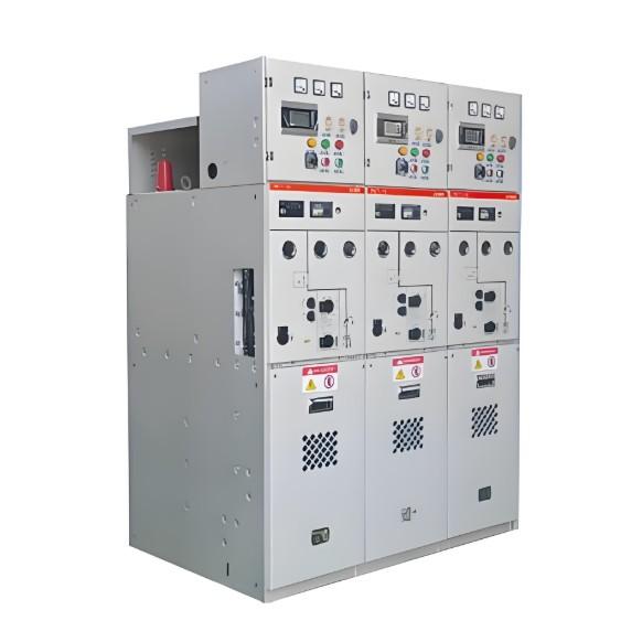
What is High Voltage Switchgear?

What is High Voltage Switchgear?
High Voltage Switchgear Definition
High voltage switchgear is defined as equipment that manages voltages above 36KV to ensure safe and efficient power distribution.

Main Components
High voltage circuit breakers, such as air blast, oil, SF6, and vacuum circuit breakers, are essential for interrupting high voltage currents.
Essential Features of High Voltage Circuit Breaker
The essential features to be provided in high voltage circuit breaker, to ensure safe and reliable operation the breakers used in high voltage switchgear, must be capable of being operated safely for,
Terminal faults.
Short line faults.
Transformer or reactors magnetizing current.
Energizing long transmission line.
Charging capacitor bank.
Switching of out of phase sequence.
Air Blast Circuit Breaker
In this design, a blast of high pressure compressed air is used to quench arc between two detaching contacts, when the arc column ionization is least at currents zero.
Oil Circuit Breaker
This is further classified as bulk oil circuit breaker (BOCB) and minimum oil circuit breaker (MOCB). In BOCB, the interrupting unit is placed inside an oil tank of earth potential. Here oil is used as both insulating and interrupting medium. In MOCB on the other hand, the insulating oil requirement can be minimized by placing the interrupting units in an insulating chamber at the live potential on an insulator column.
SF6 Circuit Breaker
SF6 gas is commonly used as an arc quenching medium in high voltage applications. Sulfur hexafluoride gas is highly electronegative, with excellent dielectric and arc quenching properties. These properties allow for high voltage circuit breakers to be designed with smaller dimensions and shorter contact gaps. Its superior insulating ability also aids in constructing indoor type switchgear for high voltage systems.
Vacuum Circuit Breaker
In a vacuum, there is no further ionization between two separated current carrying contacts, after current zero. The initial arc is caused by it will die as soon as next zero crossing but as there is no provision of further ionization once the current is crossed its first zero, the arc quenching is completed. Although the arc quenching method is very fast in VCB, but till it is not a suitable solution for high voltage switchgear, as VCB made for very high voltage level is not economical at all.
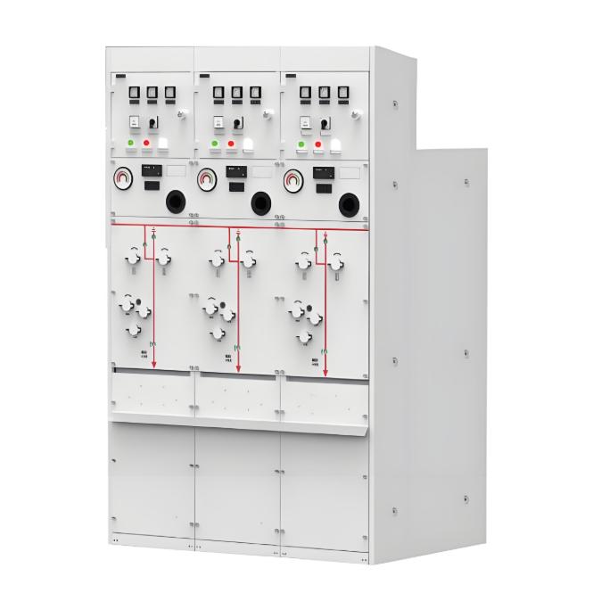
Types of Switchgear
Gas Insulated Indoor Type (GIS),
Air Insulated Outdoor Type.
Fault Management
Generally the load connected to the power system is inductive in nature. Due to this inductance, when short circuit current is just interrupted by a circuit breaker, there is a chance of high restriking voltage of high-frequency oscillation in order of few hundred Hz. This voltage has two parts
Transient recovery voltage with high frequency oscillation immediately after the arc extinction.After die down this high frequency oscillation, power frequency recover voltage appears across the CB contacts.
Transient Recovery Voltage
Just after the extinction of arc transient recovery voltage appears across the CB contacts, with high frequency. This transient recovery voltage ultimately approaches to open circuit voltage. This recovery voltage can be represented as
The frequency of oscillation is governed by the circuit parameter L and C. The resistance present in the power circuit damps out this transient voltage. The transient recovery voltage has not a single frequency, it is a combination of many different frequencies due to the complexity of the power network.

Power Frequency Recovery Voltage
This is nothing but open circuit voltage appears across the CB contacts, just after the transient recovery voltage damped out. In three phase system the power frequency recovery voltage differs in different phase. It is highest in the first phase.
If the network neutral is not earthed, the voltage across the first pole to be cleared is 1.5U where U is the phase voltage. In an earthed neutral system, it will be 1.3U. By using damping resistor, the magnitude and rate of rising of transient recovery voltage can be limited.
The dielectric recovery of the arc quenching medium and rate of rising of transient recovery voltage has great influence on the performance of the circuit breaker used in high voltage switchgear system. In an air blast circuit breaker, once ionized air is de-ionized very slowly, thus air takes a long time to recover dielectric strength.
That is why it is preferable very slowly, thus air takes a long time to recover dielectric strength. That is why it is preferable to used low-value breaker resistor to slow down the rate of rising of recovery voltage.
On the other hand ABCB is less sensitive to the initial recovery voltage because of high arc voltage in SF6 circuit breaker, the interrupting medium (SF6) has faster rate of recovery of dielectric strength, than air. Lower arc voltage makes SF6 CB more sensitive to the initial recovery voltage.
In oil circuit breaker, during arc having pressurized hydrogen gas (produced during recombination of oil due to arc temperature) provides quick recovery of dielectric strength immediate after current zero. Hence OCB is more sensitive to rate of rise of recovery voltage. It is also more sensitive to initial transient recovery voltage.
Short Line Fault
Short line fault in transmission network is defined as the short circuit faults occurred, within 5 km of the line length. Double frequency being impressed on the circuit breaker and the difference of source and line side transient recovery voltage, both voltages start from instantaneous values at the opposition of the circuit breakers prior to the interruption.
On the supply side, the voltage will oscillate at supply frequency and ultimately approaches to open circuit voltage. On the line side, after interruption, trapped charges initial traveling waves through the transmission line, since there is no driving voltage on the driving side, the voltage ultimately becomes zero because of the line losses.
Recommended