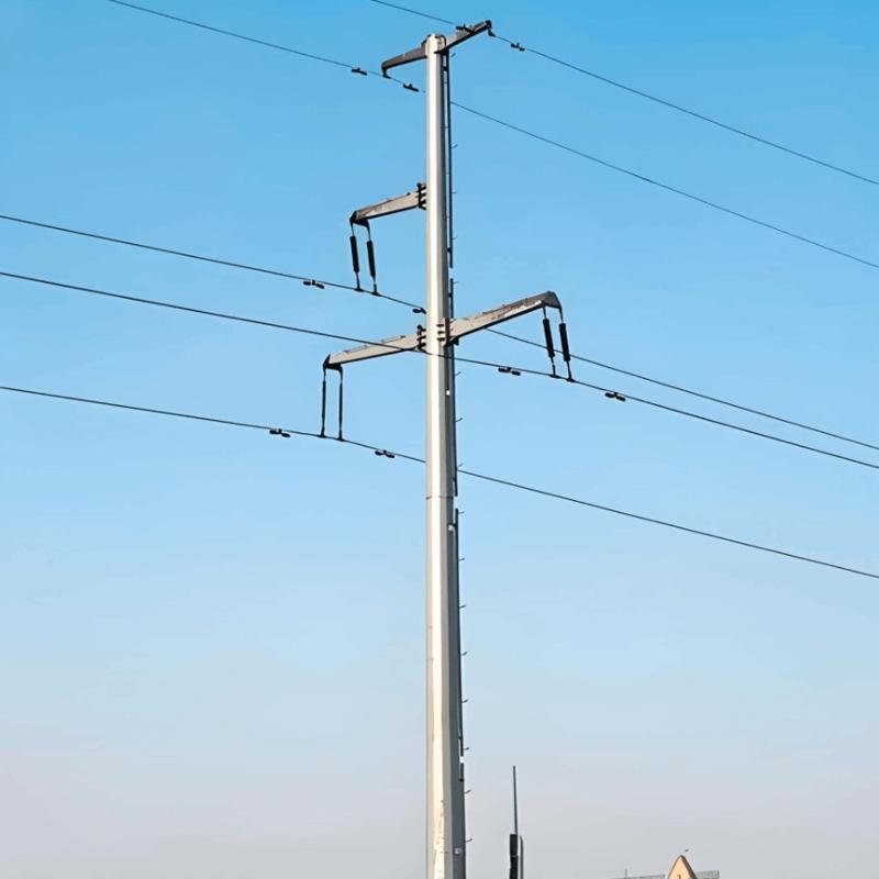
Paggamit ng mga distribution transformers para sa pagbibigay ng kuryente sa LV networks

Ang mga karakteristikong datos ng mga distribution transformers ay ditadyahan ng mga pangangailangan ng network. Ang tinukoy na effective power kailangang imultiplikahin sa power factor cosφ upang makuhang ang rated power Srt. Sa mga distribution networks, karaniwang pinapaboran ang halaga ng uk = 6%.
Paggamit ng Distribution Transformers para sa Pagbibigay ng Power sa LV Networks
Ang mga pagkawala ng transformer ay binubuo ng no - load losses at short - circuit losses. Ang no - load losses ay nagmumula sa patuloy na pagbaligtad ng magnetization sa iron core at nananatiling mahalagang constant, na walang kinalaman sa load. Ang short - circuit losses ay binubuo ng ohmic losses sa mga winding at mga pagkawala mula sa leakage fields, at sila ay proporsyonal sa square ng lebel ng load.
Ang mga pagkawala ng transformer ay binubuo ng no - load losses at short - circuit losses. Ang no - load losses ay nagmumula sa patuloy na pagbaligtad ng magnetization sa iron core. Ang mga pagkawala na ito ay mahalagang constant at hindi naapektuhan ng load.
Sa kabilang banda, ang short - circuit losses ay binubuo ng ohmic losses sa mga winding at mga pagkawala dahil sa leakage fields. Sila ay proporsyonal sa square ng magnitude ng load.
Sa teknikal na artikulong ito, ang mga pangunahing kriteria para sa piliin ng mga distribution transformers sa 50 - 2500 kVA power range para sa pagsupply ng low - voltage networks ay sasalamin.
1. Mga Rekisito sa Operational Safety
Routine Tests: Ito ay sumasaklaw sa mga item tulad ng mga pagkawala, short - circuit voltage \(u_{k}\), at voltage tests.
Type Testing: Ito ay kasama ang mga test tulad ng heating tests at surge voltage tests.
Special Tests: Ito ay kasama ang mga test tulad ng short - circuit strength tests at noise tests.
2. Mga Electrical Conditions
Short - Circuit Voltage: Pansinin ang mga tiyak na halaga at katangian nito.
Connection Symbol / Vector Group: Matuto tungkol sa relevant na impormasyon hinggil sa connection symbols at vector groups ( [Learn More](add the corresponding link here if there is one in the original text) ).
Transformation Ratio: Tukuyin ang mga parameter ng transformation ratio.
3. Mga Installation Conditions
Interior at Outside Installation: Isipin ang mga scenario ng installation ng mga transformers, kung sa loob o labas ng bahay.
Special Local Conditions: Pansinin ang impluwensya ng mga espesyal na lokal na kondisyon.
Environmental Protection Conditions: Sumunod sa mga kaukulang environmental protection requirements.
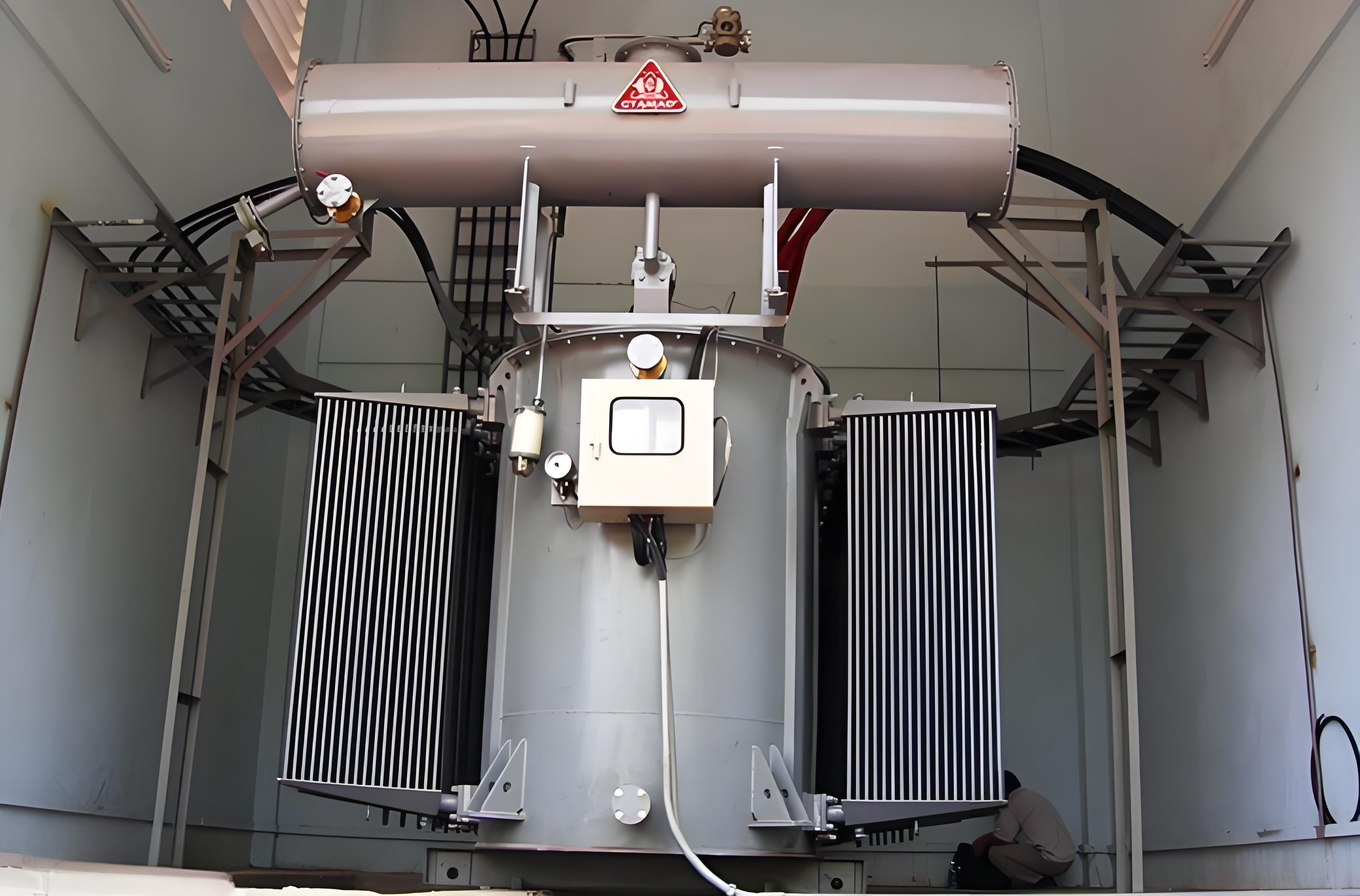
Designs: Pumili sa pagitan ng oil - immersed o resin - cast dry - type transformers.
4. Mga Operating Conditions
Loading Capacity: Para sa oil - immersed o resin - cast dry - type transformers, isipin ang kanilang load - bearing capabilities.
Load Fluctuations: Pansinin ang sitwasyon ng mga load fluctuations.
Number of Hours in Operation: Isipin ang oras ng operasyon ng mga transformers.
Efficiency: Pansinin ang efficiency ng oil - immersed o resin - cast dry - type transformers.
Voltage Regulation: Bigyan ng importansiya ang mga capability ng voltage regulation.
Parallel Transformer Operation: Matuto tungkol sa relevant na sitwasyon ng parallel transformer operation ( [Learn More](add the corresponding link here if there is one in the original text) ).
5. Mga Characteristic Data ng Transformer kasama ang mga Halimbawa
Rated Power:SrT = 1000kVA
Rated Voltage: UrOS=20 kV
Lower - side Voltage: UrUS=0.4 kV
Rated Lightning Impulse Withstand Voltage: UrB=125 kV
Loss Combination
No - load Losses: P0=1700 W
Short - circuit Losses: Pk=13000 W
Acoustical Power: LWA=73 dB
Short - circuit Voltage: uk=6%
Transformation Ratio: PV/SV=20 kV/0.4 kV
Connection Symbol: Dyn5
Termination Systems: Halimbawa, lower - voltage at upper - voltage side flange systems
Installation Location: Kung sa loob o labas ng bahay
a) May mas kaunti sa 1000 liters ng liquid dielectric
b) May higit sa 1000 liters ng liquid dielectric
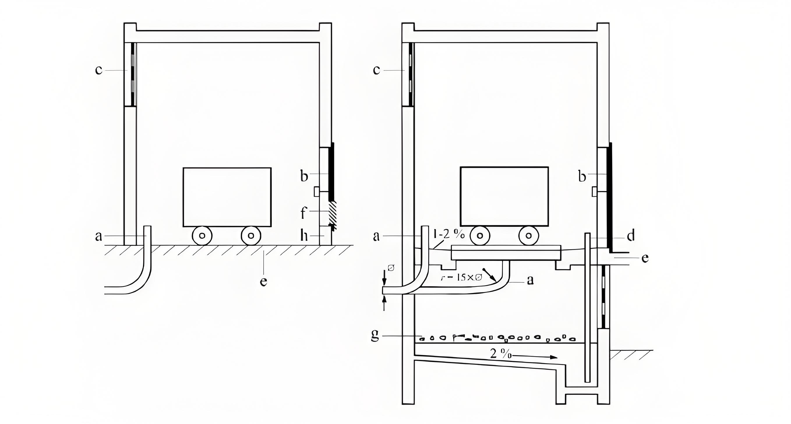
Paglalarawan
a. Cable conduit
b. Zinc - plated flat steel grate
c. Exhaust opening with protective grate
d. Unscrewed conduit with pump
e. Ramp
f. Air intake opening with protective grate
g. Gravel or crushed rock layer
h. Ledge
Ang installation ng mga transformers ay dapat protektahan mula sa groundwater at flooding. Ang cooling system ay dapat i-shield mula sa sunlight. Ang mga fire protection measures at environmental compatibility ay dapat rin na siguraduhin. Figure 1 ay nagpapakita ng isang transformer na may oil filling na mas kaunti sa 1000 liters. Sa kaso na ito, sapat na ang impermeable floor.
Para sa oil filling na higit sa 1000 liters, ang oil - collecting troughs o oil sumps ay obligatoryo.
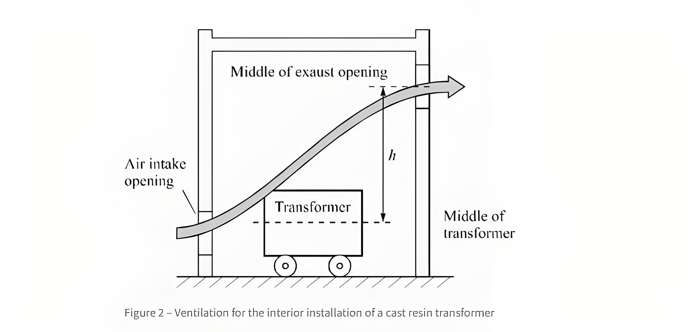
Ang laki ng exhaust opening ay ipinapakita sa Figure 2 nang walang grate para sa room heating ng 15 K.

PV=P0+k×Pk75 [kW]
Symbol Definitions:
A: Air exhaust and intake openings
P{V: Transformer power loss
k = 1.06 for oil - filled transformers
k = 1.2 for cast resin transformers
Po: No - load losses
Pk75: Short - circuit losses at (75^{\circ}\) Celsius, in kilowatts
h: Height difference, in meters
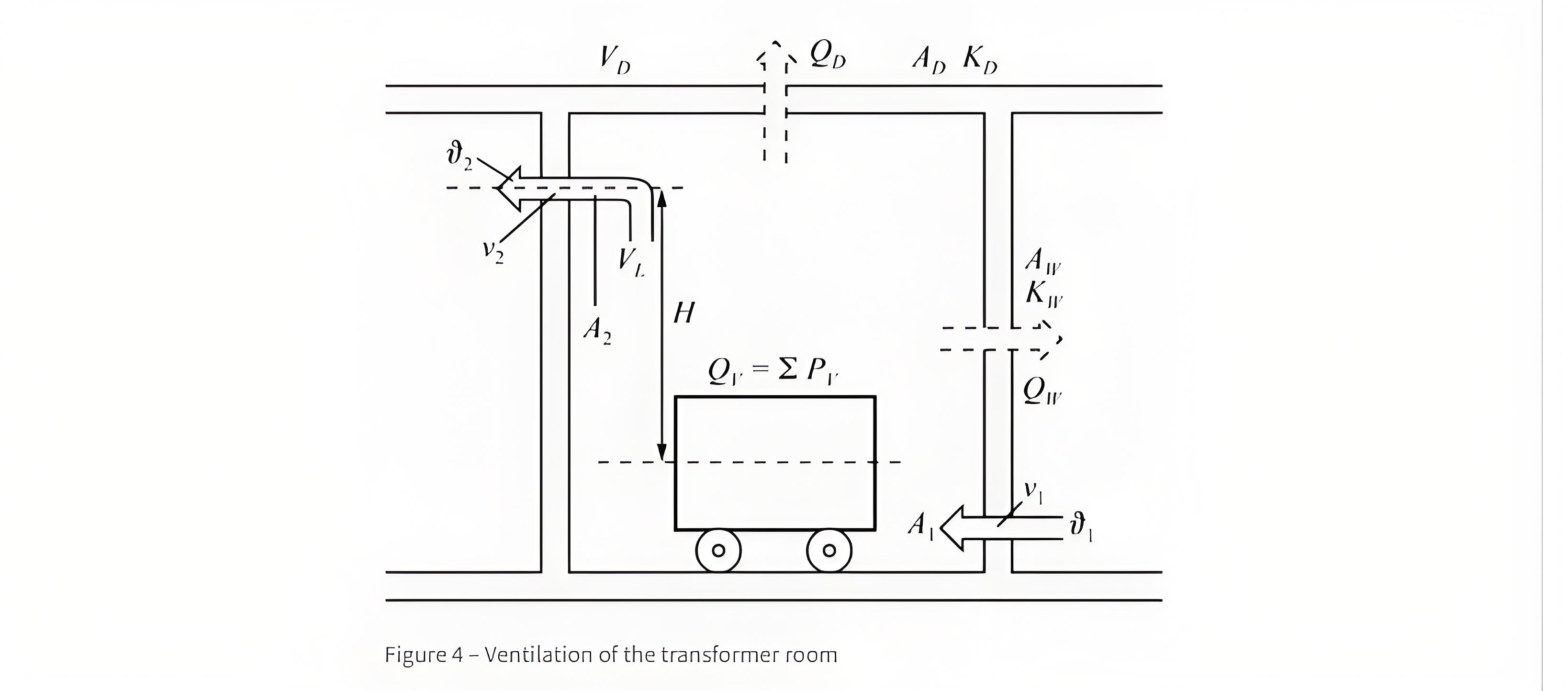
Ang mga heat losses na nabuo habang ang operasyon ng isang transformer (Figure 4) ay kailangang ilabas. Kapag ang natural ventilation ay hindi maaaring gamitin dahil sa installation conditions, mahalagang mag-install ng fan. Ang maximum allowable overall temperature ng transformer ay 40°C.
Total Losses sa isang Transformer Room
Ang kabuuang mga pagkawala sa isang transformer room ay kinalkula bilang sumusunod: Ang total losses sa transformer room ay ibinibigay ng Qloss=∑Ploss, kung saan:
Ploss=P0+1.2×Pk75×(SAF/SAN)2
Mga Path ng Heat Dissipation para sa Total Losses
Ang total losses ay nilalabas sa pamamagitan ng Qv=Qloss1+Qloss2+Qloss3
Kalkulasyon ng Heat Dissipation para sa Bawat Bahagi
Heat Dissipated by Natural Air Convection: Qloss1=0.098×A1.2×sqrtHΔuL3
Heat Dissipated by Forced Air Convection (see Figure 3): Qloss3=VL×CpL×ρ
Heat Dissipated through Walls and Ceiling (see Figure 4):Qloss2=0.7×AW×KW×ΔuW+AD×KD×ΔuD
Paglalarawan ng Meanings ng Simbolo
Pv: Transformer power loss in kW
Qv: Total heat dissipation in kW
QW,D: Heat dissipation through walls and ceiling in kW
AW,D: Area of walls and ceiling in \(m^2\)
KW,D: Heat transfer coefficient in \(kW/m^2K\)
SAF: Power for cooling type AF in kVA
SAN: Power for cooling type AN in kVA
VL: Air flow rate in \(m^3/s\) or \(m^3/h\)
Qv1: Part of heat dissipated by natural air convection in kW
Qv2: Part of heat dissipated through walls and ceiling in kW
Qv3: Part of heat dissipated by forced air convection in kW
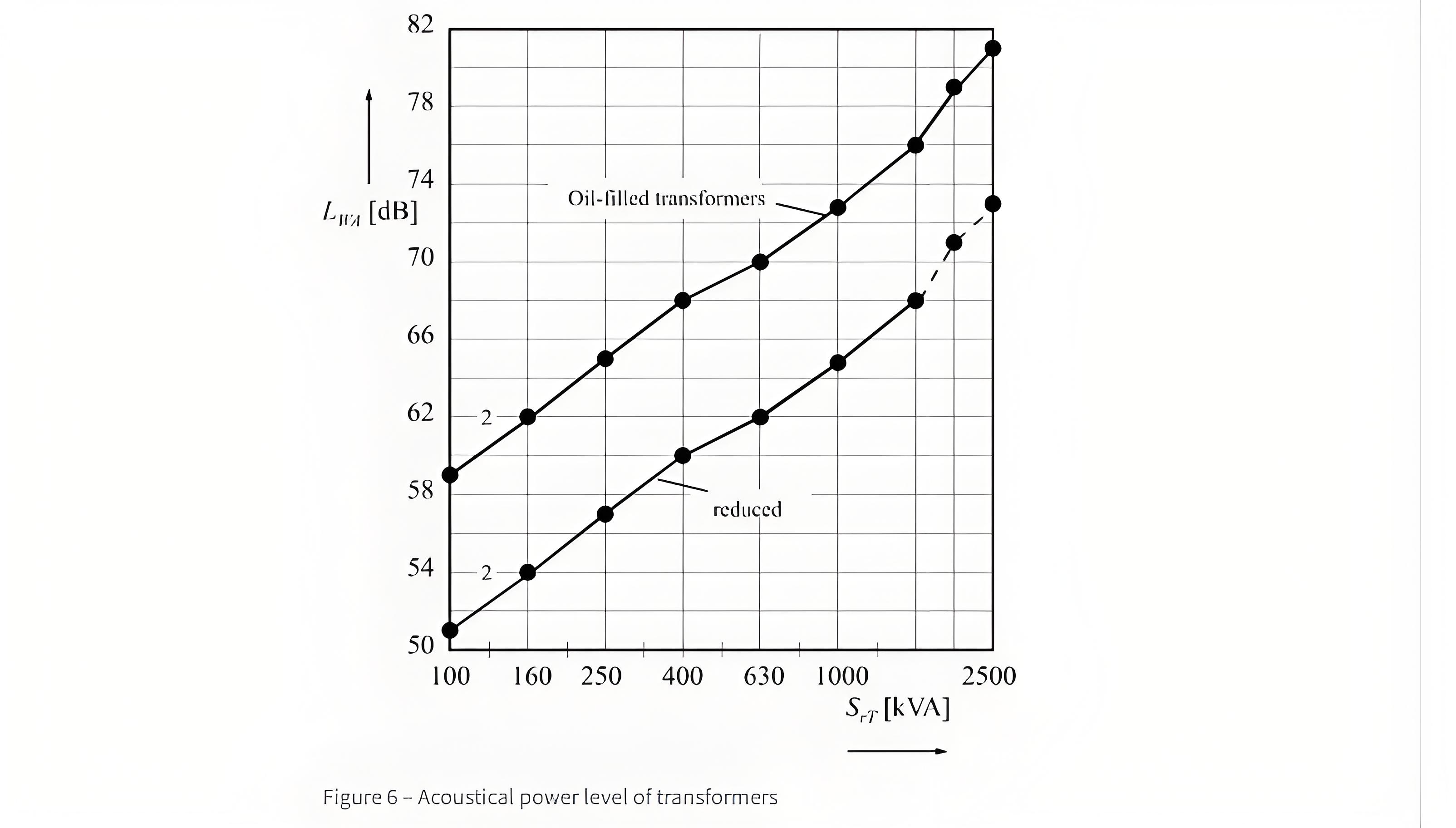
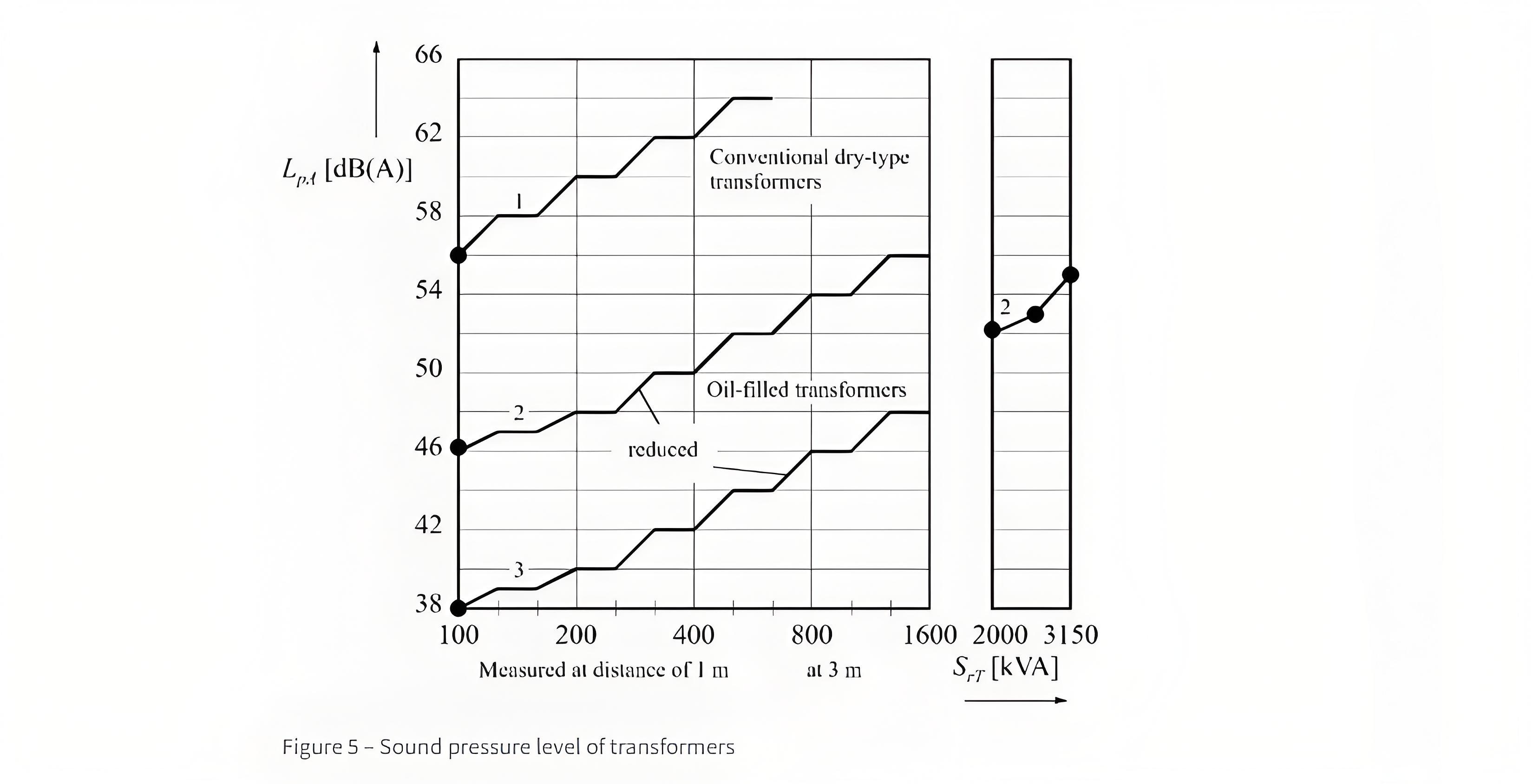
Ang Figure 5 ay nagpapakita ng mga noise levels ng iba't ibang transformers batay sa IEC Publication 551. Ang magnetic noise ay nagmumula sa mga oscillations ng iron core (na dependent sa induction) at nakasalalay sa mga katangian ng materyales ng core laminations.
Ang acoustical power (Figure 6) ay isang sukat ng noise level na ginagawa ng isang acoustical source.