Selection of distribution transformers for supplying power to LV networks

The characteristic data of distribution transformers are dictated by the requirements of the network. The determined effective power must be multiplied by the power factor cosφ to obtain the rated power Srt. In distribution networks, a value of uk = 6% is commonly preferred.
Selection of Distribution Transformers for Supplying Power to LV Networks
Transformer losses consist of no - load losses and short - circuit losses. No - load losses stem from the continuous reversal of magnetization in the iron core and remain essentially constant, being independent of the load. Short - circuit losses comprise ohmic losses in the windings and losses resulting from leakage fields, and they are proportional to the square of the load level.
Transformer losses are composed of no - load losses and short - circuit losses. No - load losses arise from the continuous reversal of magnetization in the iron core. These losses are essentially constant and unaffected by the load.
Short - circuit losses, on the other hand, consist of ohmic losses in the windings and losses caused by leakage fields. They are proportional to the square of the load magnitude.
In this technical article, the key criteria for selecting distribution transformers within the 50 - 2500 kVA power range for powering low - voltage networks will be discussed.
1. Operational Safety Requirements
Routine Tests: These cover items such as losses, short - circuit voltage \(u_{k}\), and voltage tests.
Type Testing: This includes tests like heating tests and surge voltage tests.
Special Tests: These involve tests such as short - circuit strength tests and noise tests.
2. Electrical Conditions
Short - Circuit Voltage: Pay attention to its specific values and characteristics.
Connection Symbol / Vector Group: Learn about relevant information regarding connection symbols and vector groups ( [Learn More](add the corresponding link here if there is one in the original text) ).
Transformation Ratio: Determine the parameters of the transformation ratio.
3. Installation Conditions
Interior and Outside Installation: Consider the installation scenarios of transformers, whether indoors or outdoors.
Special Local Conditions: Take note of the influence of special local conditions.
Environmental Protection Conditions: Comply with corresponding environmental protection requirements.
Designs: Choose between oil - immersed or resin - cast dry - type transformers.
4. Operating Conditions
Loading Capacity: For oil - immersed or resin - cast dry - type transformers, consider their load - bearing capabilities.
Load Fluctuations: Pay attention to the situation of load fluctuations.
Number of Hours in Operation: Take into account the operating duration of transformers.
Efficiency: Focus on the efficiency of oil - immersed or resin - cast dry - type transformers.
Voltage Regulation: Attach importance to the voltage regulation capabilities.
Parallel Transformer Operation: Learn about the relevant situations of parallel transformer operation ( [Learn More](add the corresponding link here if there is one in the original text) ).
5. Transformer Characteristic Data with Examples
Rated Power:SrT = 1000kVA
Rated Voltage: UrOS=20 kV
Lower - side Voltage: UrUS=0.4 kV
Rated Lightning Impulse Withstand Voltage: UrB=125 kV
Loss Combination
No - load Losses: P0=1700 W
Short - circuit Losses: Pk=13000 W
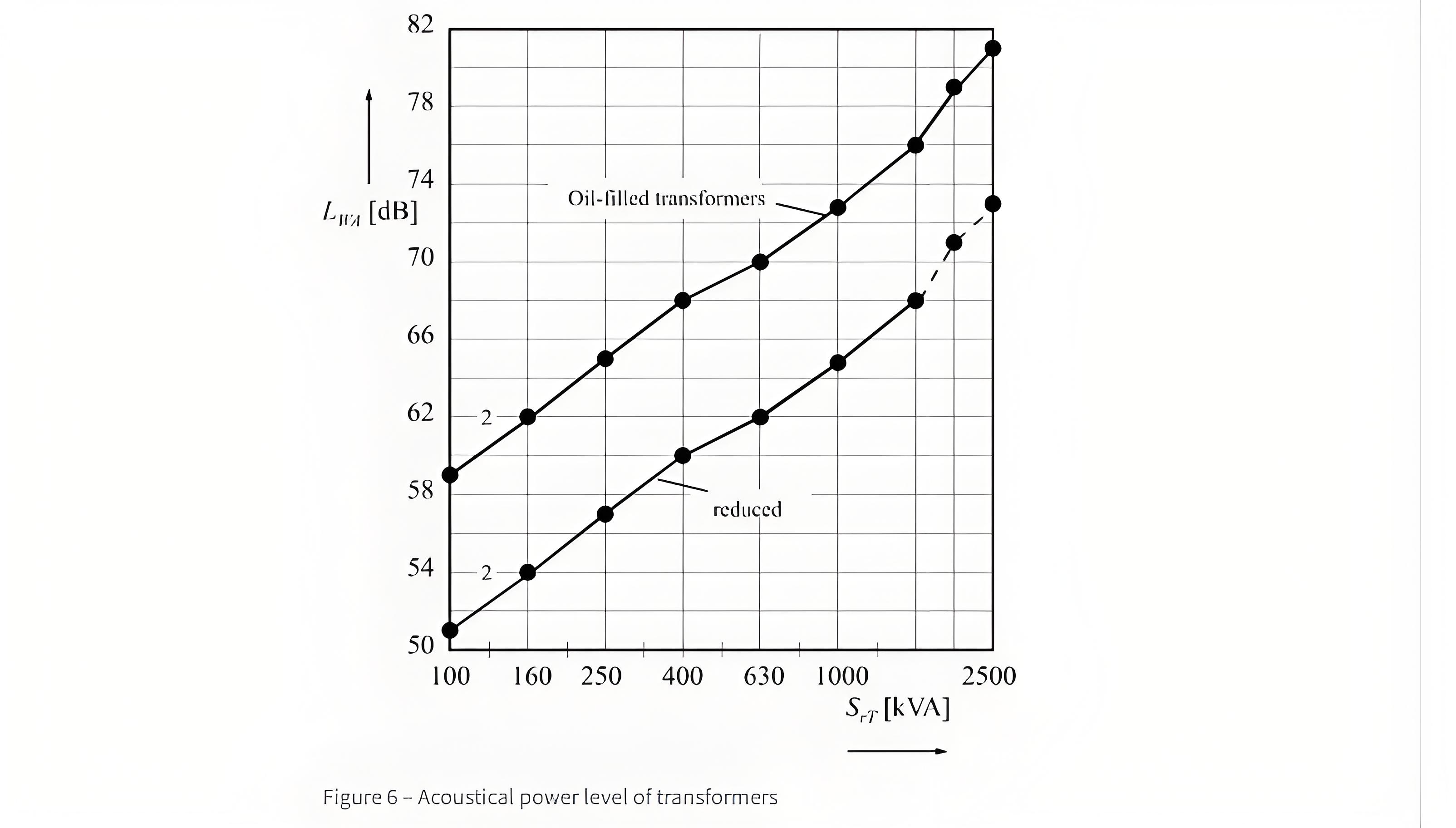
Acoustical Power: LWA=73 dB
Short - circuit Voltage: uk=6%
Transformation Ratio: PV/SV=20 kV/0.4 kV
Connection Symbol: Dyn5
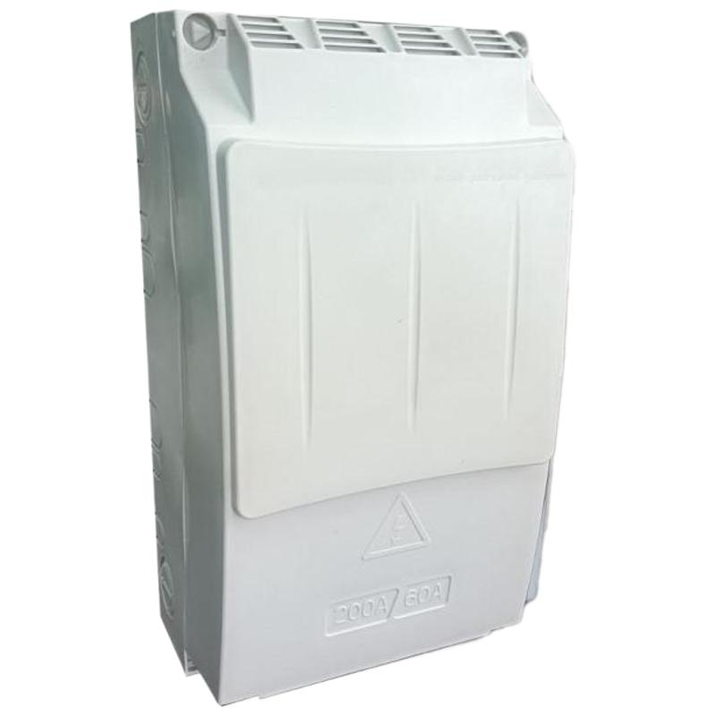
Termination Systems: For example, lower - voltage and upper - voltage side flange systems
Installation Location: Whether indoor or outdoor
a) With less than 1000 liters of liquid dielectric
b) With more than 1000 liters of liquid dielectric
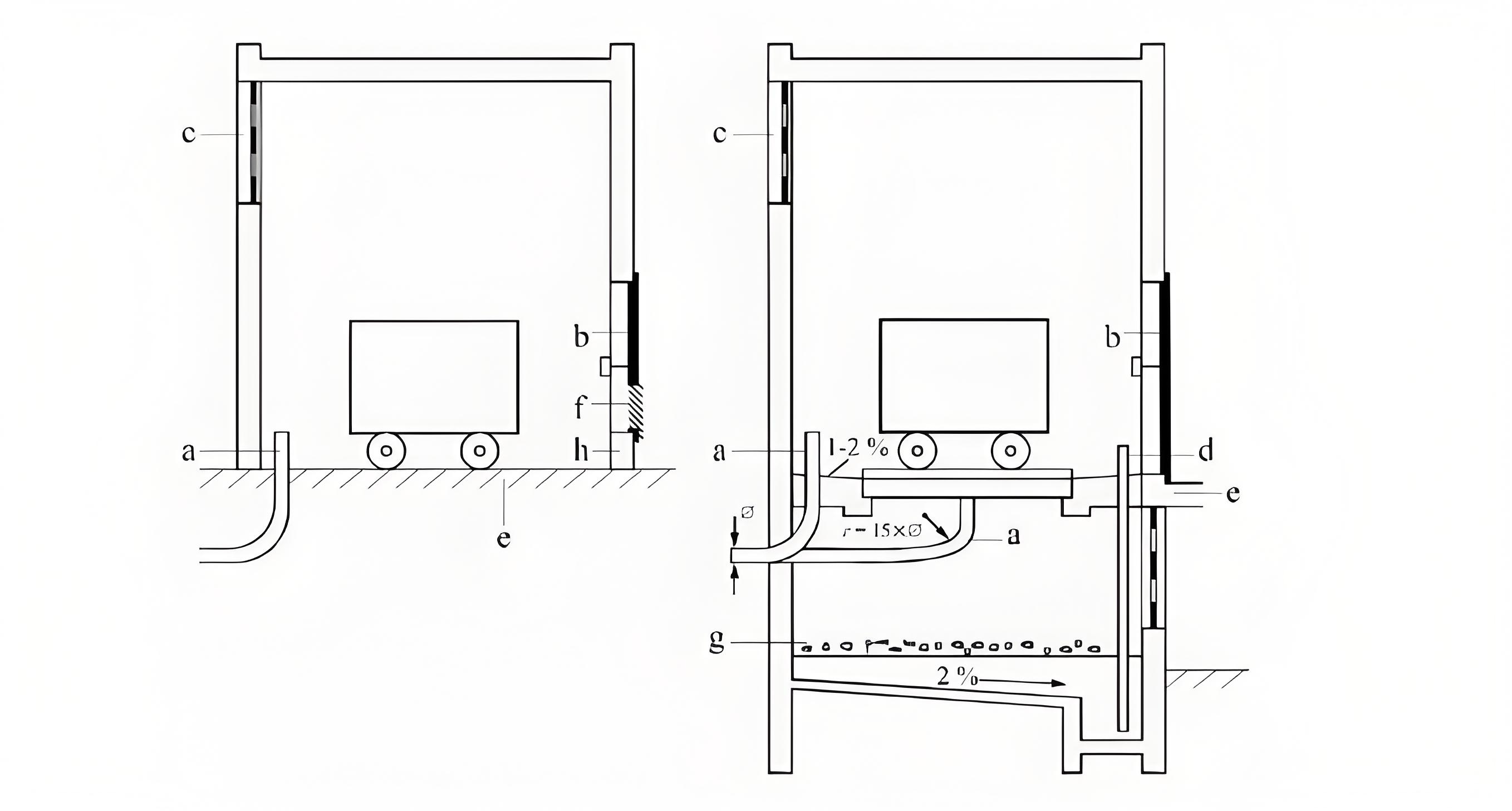
Explanation
a. Cable conduit
b. Zinc - plated flat steel grate
c. Exhaust opening with protective grate
d. Unscrewed conduit with pump
e. Ramp
f. Air intake opening with protective grate
g. Gravel or crushed rock layer
h. Ledge
The installation of transformers should be protected from groundwater and flooding. The cooling system must be shielded from sunlight. Fire protection measures and environmental compatibility must also be guaranteed. Figure 1 shows a transformer with an oil filling of less than 1000 liters. In this case, an impermeable floor is sufficient.
For an oil filling of more than 1000 liters, oil - collecting troughs or oil sumps are mandatory.
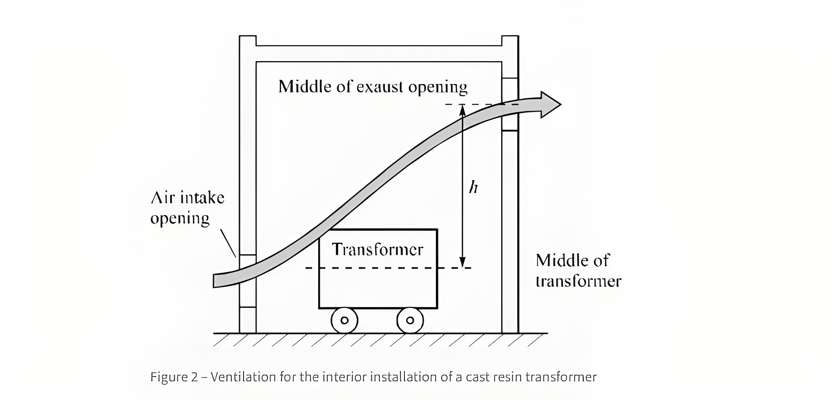
The size of the exhaust opening is shown without grate in Figure 2 for a room heating of 15 K.

PV=P0+k×Pk75 [kW]
Symbol Definitions:
A: Air exhaust and intake openings
P{V: Transformer power loss
k = 1.06 for oil - filled transformers
k = 1.2 for cast resin transformers
Po: No - load losses
Pk75: Short - circuit losses at (75^{\circ}\) Celsius, in kilowatts
h: Height difference, in meters
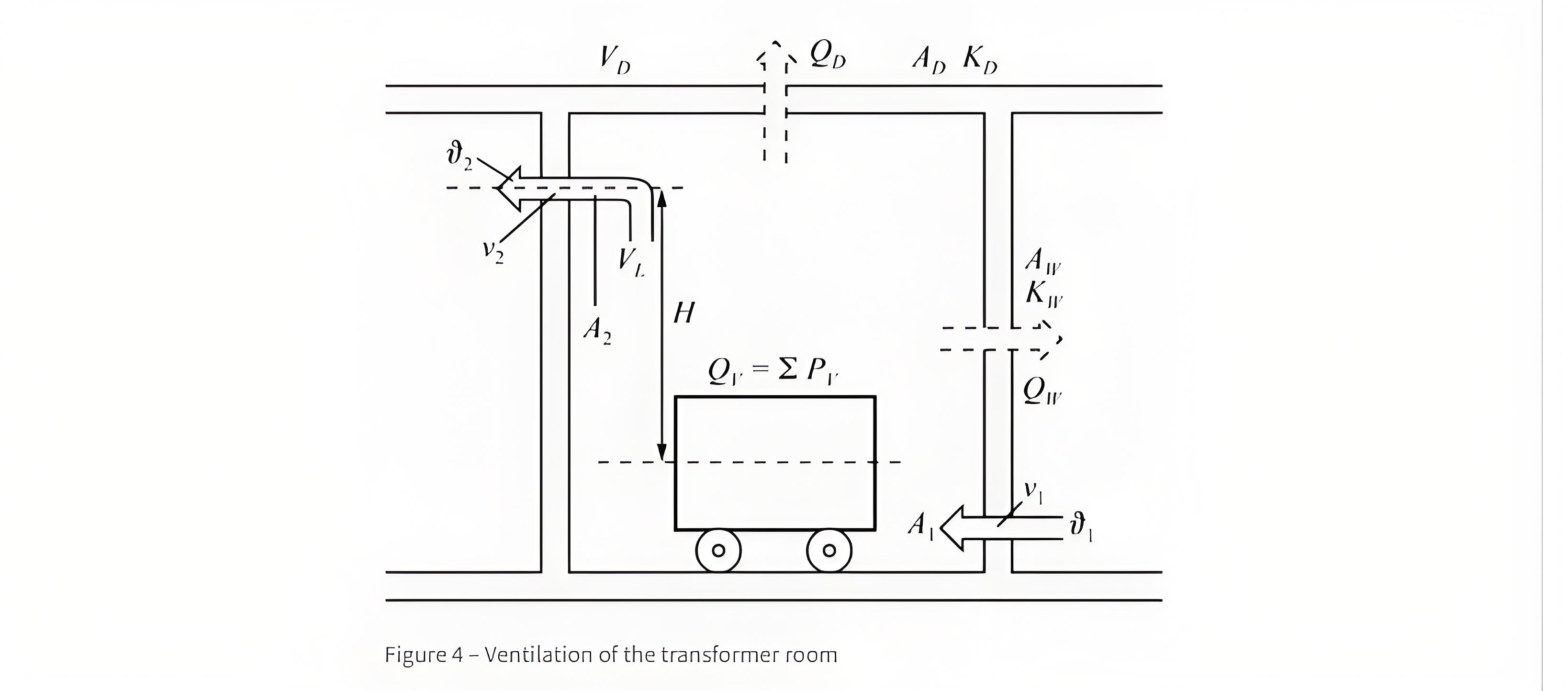
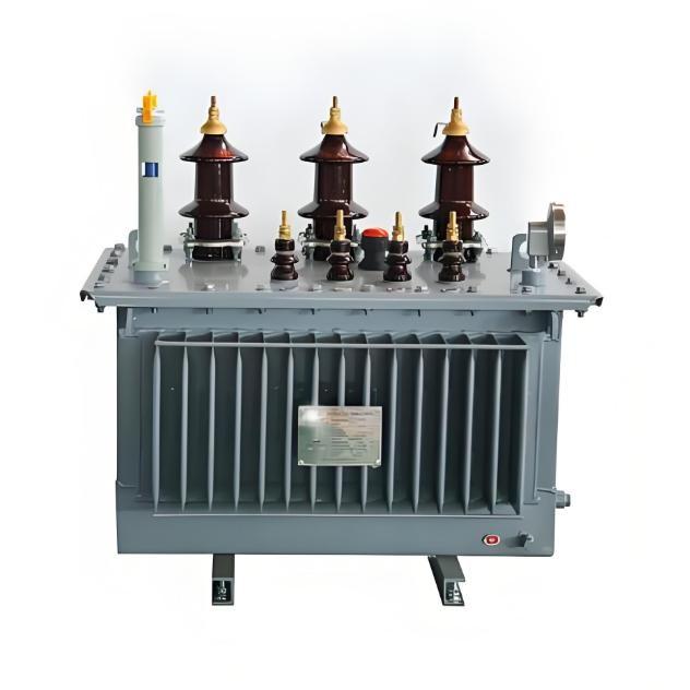
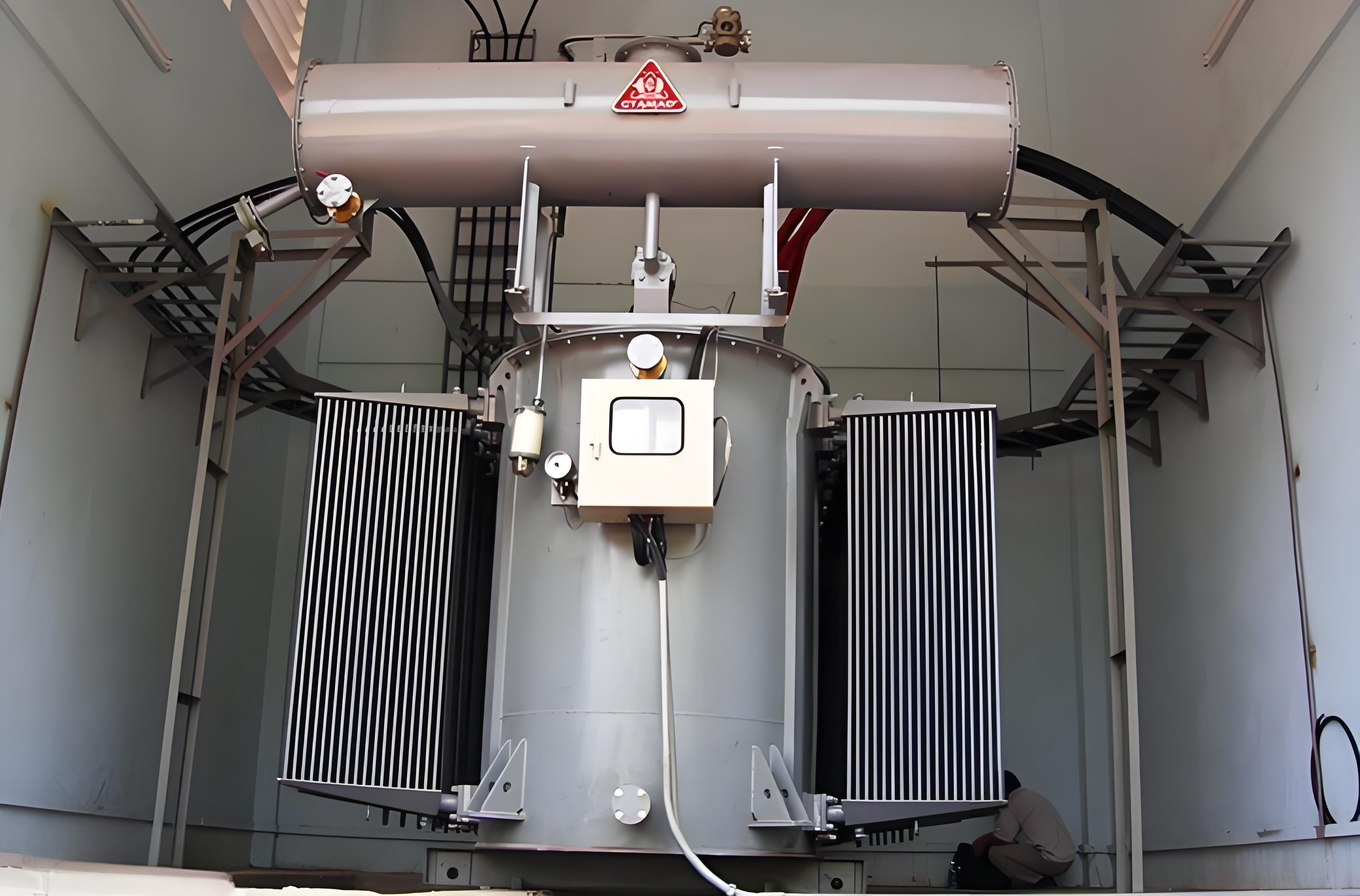
The heat losses generated during the operation of a transformer (Figure 4) need to be dissipated. When natural ventilation cannot be used due to installation conditions, it is essential to install a fan. The maximum allowable overall temperature of the transformer is 40°C.
Total Losses in a Transformer Room
The overall losses in a transformer room are calculated as follows: The total losses in the transformer room are given by Qloss=∑Ploss, where:
Ploss=P0+1.2×Pk75×(SAF/SAN)2
Heat Dissipation Paths for Total Losses
Total losses are dissipated through Qv=Qloss1+Qloss2+Qloss3
Calculation of Heat Dissipation for Each Part
Heat Dissipated by Natural Air Convection: Qloss1=0.098×A1.2×sqrtHΔuL3
Heat Dissipated by Forced Air Convection (see Figure 3): Qloss3=VL×CpL×ρ
Heat Dissipated through Walls and Ceiling (see Figure 4):Qloss2=0.7×AW×KW×ΔuW+AD×KD×ΔuD
Explanation of Symbol Meanings
Pv: Transformer power loss in kW
Qv: Total heat dissipation in kW
QW,D: Heat dissipation through walls and ceiling in kW
AW,D: Area of walls and ceiling in \(m^2\)
KW,D: Heat transfer coefficient in \(kW/m^2K\)
SAF: Power for cooling type AF in kVA
SAN: Power for cooling type AN in kVA
VL: Air flow rate in \(m^3/s\) or \(m^3/h\)
Qv1: Part of heat dissipated by natural air convection in kW
Qv2: Part of heat dissipated through walls and ceiling in kW
Qv3: Part of heat dissipated by forced air convection in kW
Figure 5 presents the noise levels of various transformers as per IEC Publication 551. Magnetic noise stems from the oscillations of the iron core (which is induction - dependent) and hinges on the material properties of the core laminations.
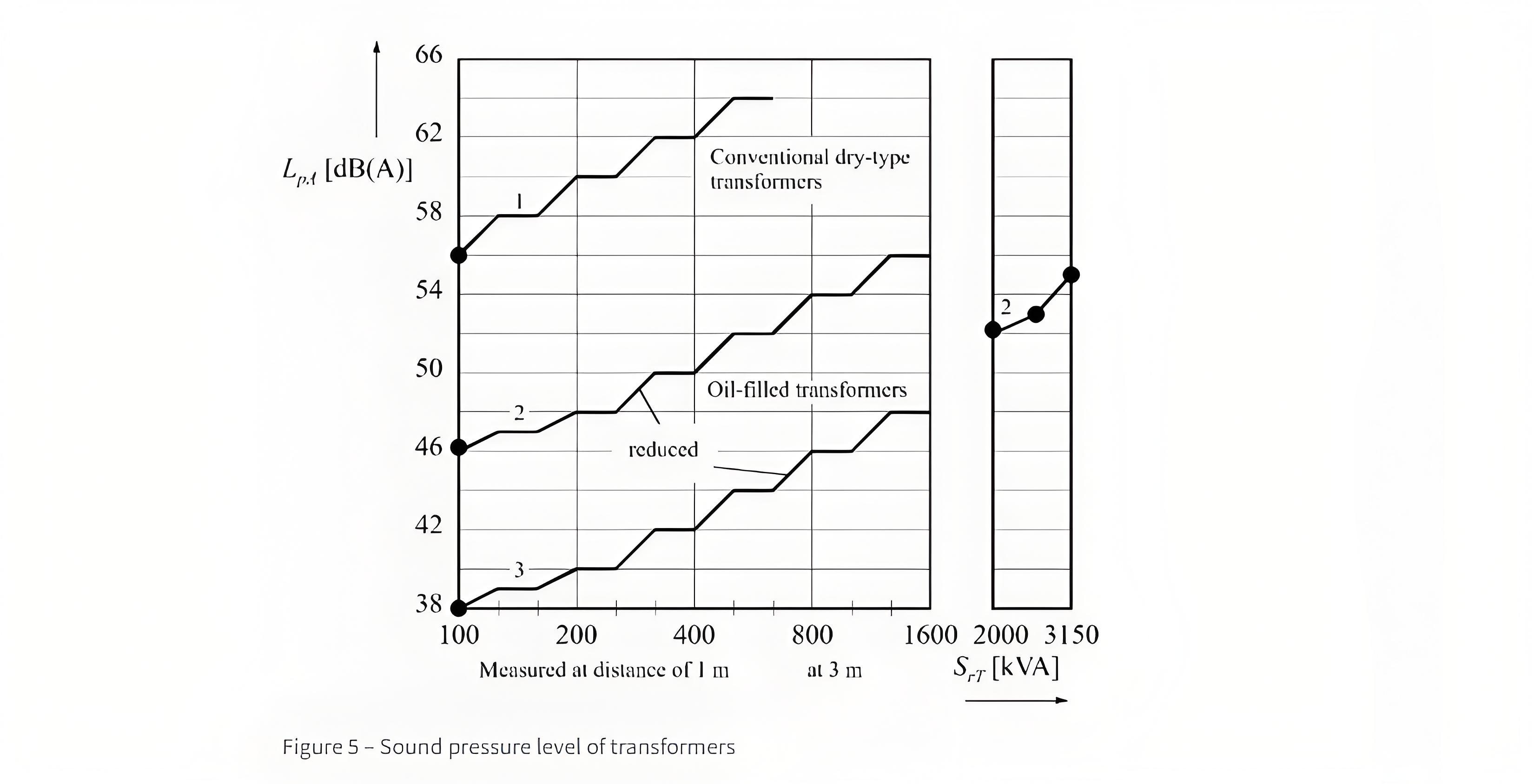
The acoustical power (Figure 6) is a measure of the noise level produced by an acoustical source.