1.Linear Regulators vs. Switching Regulators
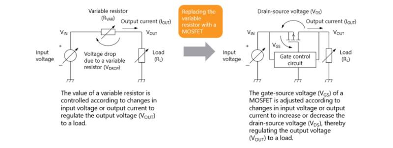
A linear regulator requires an input voltage higher than its output voltage. It handles the difference between input and output voltages—known as the dropout voltage—by varying the impedance of its internal regulating element (such as a transistor).
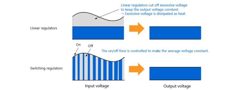
Think of a linear regulator as a precise “voltage control expert.” When faced with excessive input voltage, it decisively “acts” by “cutting off” the portion exceeding the desired output level, ensuring the output voltage remains constant. The excess voltage that is “trimmed away” is ultimately dissipated as heat, maintaining a stable output.
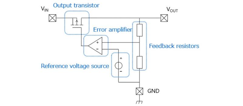
In terms of circuit configuration, a typical series linear regulator uses an error amplifier, a reference voltage source, and a pass transistor to form a closed-loop feedback system that continuously monitors and corrects the output voltage in real time.
Linear regulators mainly include three-terminal regulators and LDO (Low Dropout) regulators. The former uses a conventional architecture requiring a relatively large input-to-output voltage difference (typically ≥2 V), resulting in lower efficiency, and is suitable for medium- to high-power applications. In contrast, LDO regulators are optimized for minimal dropout voltage (as low as 0.1 V), making them ideal for scenarios where the input and output voltages are close—such as in battery-powered devices—though careful thermal design is required.
Figure 1 illustrates the operating principles of linear and switching regulators.
Switching regulators, on the other hand, control the conduction and turn-off timing of power switches (e.g., MOSFETs) to adjust the duty cycle of energy transfer. The input voltage is then converted into a stable average output voltage through energy storage and filtering by inductors and capacitors.
Their core characteristic is “chopper-style” regulation: the input voltage is chopped at high frequency, and the energy delivered to the output is controlled by adjusting the switch duty cycle. This approach achieves significantly higher efficiency compared to linear regulators.
Common topologies of switching regulators include Buck (step-down), Boost (step-up), and others, supporting wide input voltage ranges and making them well-suited for high-power applications or environments with significant input voltage fluctuations.
Figure 2 provides a comparison between linear and switching regulators. You can select the appropriate type based on your specific needs: choose a linear regulator when low noise and circuit simplicity are priorities; opt for a switching regulator when high efficiency and high power delivery are required.
| Characteristics |
Linear Regulator |
Switching Regulator |
| Efficiency |
Low (high loss when voltage difference is large) |
High (80%-95%) |
| Heat Dissipation Requirement |
Heat sink required (heat is dissipated directly) |
Low (heat is generated indirectly by switching loss) |
| Noise |
Pure output, no high-frequency ripple |
Switching noise exists, filter optimization required |
| Application Scenarios |
Low-power, high-precision power supply (e.g., sensors) |
High-power, wide-voltage input (e.g., power modules) |
2.Series Voltage Regulators
A series voltage regulator is positioned between the power source and the load, acting like a precise “voltage regulation guardian.” Its operating principle involves dynamically adjusting the resistance of a variable resistor in response to changes in input voltage or output current, thereby maintaining the output voltage at a stable, preset value.
In modern electronic technology, series regulator ICs use active devices—such as MOSFETs or bipolar junction transistors (BJTs)—to elegantly replace traditional variable resistors, significantly enhancing the regulator’s performance and reliability.
The circuit configuration of a series voltage regulator is precise and well-structured, primarily consisting of the following four core components:
● Output Transistor: Connected in series between the input and output pins of the regulator, it acts like a bridge linking the upstream power source and downstream load. When fluctuations occur in the input voltage or output current, the signal from the error amplifier precisely controls the gate voltage (for MOSFETs) or base current (for BJTs) of this transistor.
● Reference Voltage Source: Serving as the stable benchmark for the error amplifier, the reference voltage source plays a critical role. The error amplifier relies on this fixed reference to accurately regulate the gate or base of the output transistor, thereby ensuring a stable output voltage.
● Feedback Resistors: These resistors divide the output voltage to generate a feedback voltage. The error amplifier compares this feedback voltage with the reference voltage to achieve precise output regulation. The two feedback resistors are connected in series between the VOUT and GND pins, and the voltage at their midpoint is fed into the error amplifier.
● Error Amplifier: Functioning as the “intelligent brain” of the series regulator, the error amplifier carefully compares the feedback voltage (i.e., the voltage at the midpoint of the feedback resistor divider) with the reference voltage. If the feedback voltage falls below the reference voltage, the error amplifier increases the drive strength to the MOSFET, reducing its drain-source voltage and thereby raising the output voltage. Conversely, if the feedback voltage exceeds the reference voltage, the amplifier reduces the MOSFET’s drive strength, increasing the drain-source voltage and lowering the output voltage accordingly.
In this article, we have further explored the working principles, functions, and circuit configurations of several types of voltage regulators. In the next installment, we will explain the dynamic regulation mechanism of linear regulators and clarify the differences between three-terminal regulators and LDO (Low Dropout) regulators.

 Login