What should be noted when choosing a current transformer for a 10kV station transformer circuit?

Practical Experience Sharing from an Electrical Engineer in the Field
By James, 10 Years in the Electrical Industry
Hi everyone, I'm James, and I've been working in the electrical industry for 10 years.
From early involvement in substation design and equipment selection, to later taking charge of relay protection and automation system commissioning for entire projects, one of the most frequently used devices in my work has been the current transformer (CT).
Recently, a friend who's just starting out asked me:
“What should I pay attention to when selecting current transformers for 10kV station transformer circuits?”
Great question! Many people think choosing a CT is all about the rated current ratio — but to truly match the needs of a circuit, you need to consider multiple factors.
Today, I’ll share with you in simple language — based on my hands-on experience over the past few years — what key points to consider when selecting CTs for 10kV station transformer circuits, what each parameter means, and how to make the right choice.
No complicated jargon, no endless standards — just practical knowledge you can use in real life.
1. Why Is It Important to Carefully Choose CTs for Station Transformer Circuits?
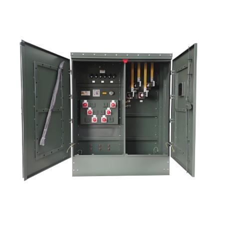
Although the station service transformer isn't the main power transformer, it plays a critical role in supplying internal power within a substation — including control power, lighting, maintenance power, and UPS systems.
If the station transformer fails or its protection malfunctions, it could lead to:
Loss of control power;
DC system losing charging capability;
The entire substation shutting down.
And since the current transformer is the core component for protection and measurement, its selection directly affects whether the protection is reliable and the measurements are accurate.
So, choosing the right CT = safety + reliability + cost-effectiveness.
2. Six Key Points When Selecting CTs for 10kV Station Transformer Circuits
Based on my 10 years of field experience and project practice, here are the six most important considerations:
Point 1: Rated Primary and Secondary Current
Purpose: Ensure the CT operates normally and meets protection sensitivity requirements.
This is the most basic and important parameter.
Common combinations:
Primary current: 50A, 75A, 100A, 150A (depending on station transformer capacity)
Secondary current: 5A or 0.5A (most modern protection devices use 0.5A)
My advice:
Usually choose primary current as 1.2~1.5 times the station transformer’s rated current;
For microprocessor-based protection, prefer 0.5A output to reduce secondary load;
Avoid selecting too high a rating — otherwise accuracy may be poor at low currents, affecting protection performance.
Point 2: Accuracy Class Matching the Application
Purpose: Ensure different functions (like protection, measurement, metering) receive accurate signals.
Different applications require different accuracy levels.
Common classes:
Measurement winding: Class 0.5
Metering winding: Class 0.2S
Protection winding: 5P10, 5P20, 10P10, etc.
My experience:
Station transformer circuits usually don’t require high-precision metering unless there's billing involved;
Protection windings must maintain linearity during short circuits;
Multi-winding CTs offer more flexibility and are recommended.
Point 3: Rated Output Capacity (VA Value)
Purpose: Ensure the CT can drive the connected meters or protection devices.
Insufficient capacity can cause voltage drop, affecting measurement accuracy or protection operation.
Calculation formula:
Total Load = Cable Impedance + Instrument/Protection Device Input Impedance
My advice:
Typically choose between 10–30 VA;
Microprocessor protection devices consume less power — lower capacity acceptable;
If the secondary cable is long (e.g., over 50 meters), increase the capacity appropriately;
Don’t blindly select high capacity — avoid core saturation.
Point 4: Thermal and Dynamic Stability Check
Purpose: Ensure the CT can withstand short-circuit current without damage.
In 10kV systems, short-circuit currents can reach thousands of amps.
How to do it:
Check maximum short-circuit current (Ik);
Verify CT thermal stability current (It) and dynamic stability current (Idyn);
Generally, It ≥ Ik (for 1 second), Idyn ≥ 2.5 × Ik
Real case: I once had a CT explode after a short circuit — turned out the dynamic stability current didn’t meet system requirements. Replacing with a higher-rated CT solved the problem.
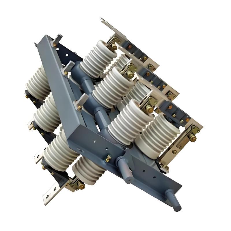
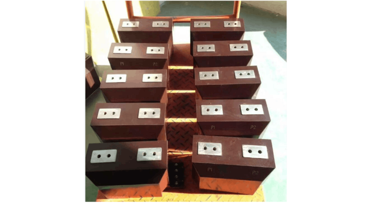
Point 5: Installation Method and Structure Type
Purpose: Ensure the CT is easy to install and maintain, and fits the available space.
Common CT types include:
Core-type (common in switchgear)
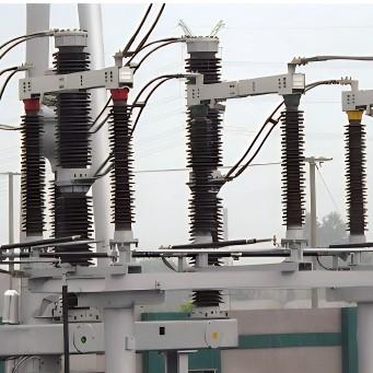
Post-type (suitable for outdoor use)
Bushing-type (often used on transformers)
My advice:
In 10kV switchgear, core-type CTs are most common;
Make sure the conductor size matches the core hole diameter;
For tight spaces, consider split-core CTs for easier installation and removal;
In humid or corrosive environments, choose moisture-resistant or corrosion-proof models.
Point 6: Polarity and Wiring Method
Purpose: Ensure the signal direction to protection relays and instruments is correct, avoiding misjudgment.
Incorrect polarity can lead to:
Misoperation or failure of protection;
Wrong power flow direction judgment;
False alarms in differential protection.
My experience:
All CTs should clearly mark polarity terminals (P1, P2);
Use subtractive polarity connection consistently;
Always perform a polarity test after installation or maintenance;
Use a dedicated polarity tester or DC method for verification.
3. Other Practical Tips
In addition to the six key points above, here are some other important notes:
Multi-winding Configuration:
Separate windings for protection, measurement, and metering to avoid interference;
Reserve spare windings for future expansion.
Excitation Characteristics:
Especially for protection windings, good excitation characteristics improve protection reliability;
If possible, perform an excitation curve test to confirm core performance.
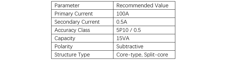
Sample Selection Reference for a 50kVA Station Transformer
4. My Final Suggestions
As someone with 10 years of field experience, I want to remind all professionals:
“Don’t just look at the model number — always consider the actual circuit, protection setup, and installation environment when selecting a CT.”
Especially in seemingly "simple" 10kV station transformer circuits, improper selection often leads to serious consequences.
Here are my recommendations for different roles:
For Maintenance Personnel:
Learn how to read CT nameplate information;
Understand basic parameter meanings;
Be familiar with polarity testing methods;
Report any abnormalities promptly.
For Technical Staff:
Master CT selection calculation methods;
Understand protection winding characteristics;
Know how to interpret system short-circuit parameters;
Be able to analyze excitation curves.
For Managers or Procurement Teams:
Clearly define technical specifications;
Choose reputable manufacturers with stable quality;
Request full test reports from suppliers;
Maintain equipment records for traceability.
5. Closing Thoughts
Current transformers may look small, but they are the eyes and ears of the entire power system.
They’re not just about reducing current — they’re the basis for protection, the foundation for metering, and the guarantee of safety.
After 10 years in the electrical field, I often say:
“Details determine success or failure, and proper selection ensures safety.”
If you ever run into difficulties selecting CTs, dealing with frequent protection misoperations, or unsure if your parameters are suitable, feel free to reach out — I’m happy to share more hands-on experience and solutions.
May every current transformer operate stably and safely, safeguarding the accuracy and reliability of our power grid!
— James