• Product
  • Suppliers
  • Manufacturers
  • Solutions
  • Free tools
  • Knowledges
  • Experts
  • Communities
Search


Why 3-Phase Power? Why Not 6, 12 or More for Power Transmission?

Edwiin
Edwiin
Field: Power switch
China

It is well-known that single-phase and three-phase systems are the most prevalent configurations for power transmission, distribution, and end-use applications. While both serve as fundamental power supply frameworks, three-phase systems offer distinct advantages over their single-phase counterparts.

Notably, multi-phase systems (such as 6-phase, 12-phase, etc.) find specific applications in power electronics—particularly in rectifier circuits and variable frequency drives (VFDs)—where they effectively reduce ripple in pulsating DC outputs. Achieving multi-phase configurations (e.g., 6, 9, or 12 phases) historically involved complex phase-shifting techniques or motor-generator sets, but these approaches remain economically infeasible for large-scale power transmission and distribution over extended distances.

Why 3-Phase Instead of 1-Phase Supply System?

The main advantage of three phase over a single phase or two phase system is that we can transmit more (constant and uniform) power.

Power in Single Phase System

  • P =  V . I  . CosФ

Power in Three Phase System

  • P = √3 . VL . IL . CosФ … Or

  • P = 3 x. VPH . IPH . CosФ

Where:

  • P = Power in Watts

  • VL = Line Voltage

  • IL = Line Current

  • VPH = Phase Voltage

  • IPH = Phase Current

  • CosФ = Power factor

It is evident that the power capacity of a three-phase system is 1.732 (√3) times higher than that of a single-phase system. By comparison, a two-phase supply transmits 1.141 times more power than a single-phase configuration.

A key advantage of three-phase systems is the rotating magnetic field (RMF), which enables self-starting in three-phase motors while ensuring constant instantaneous power and torque. In contrast, single-phase systems lack an RMF and exhibit pulsating power, limiting their performance in motor applications.

Three-phase systems also offer superior transmission efficiency, with reduced power loss and voltage drop. For instance, in a typical resistive circuit:

Single Phase System

  • Power loss in transmission line = 18I2r … (P = I2R)

  • Voltage drop in transmission line = I.6r … (V = IR)

Three Phase System

  • Power loss in transmission line = 9I2r … (P = I2R)

  • Voltage drop in transmission line = I.3r … (V = IR)

It is shown that the voltage drop and power loss in a three-phase system are 50% lower than those in a single-phase system.

Two-phase supplies, similar to three-phase ones, can provide constant power, generate RMF (rotating magnetic field), and offer constant torque. However, three-phase systems carry more power than two-phase systems due to the extra phase. This raises the question: why not use more phases like 6, 9, 12, 24, 48, etc.? We will discuss this in detail and explain how a three-phase system can transmit more power than a two-phase system with the same number of wires.

Why Not Two-Phase?

Both two-phase and three-phase systems can generate rotating magnetic fields (RMF) and provide constant power and torque, but three-phase systems offer a key advantage: higher power capacity. The extra phase in three-phase setups allows for 1.732 times more power transmission than two-phase systems with the same conductor size.

Two-phase systems typically require four wires (two phase conductors and two neutrals) to complete circuits. Using a common neutral to form a three-wire system reduces wiring, but the neutral must carry combined return currents from both phases—needing thicker conductors (e.g., copper) to avoid overheating. In contrast, three-phase systems use three wires for balanced loads (delta configuration) or four wires for unbalanced loads (star configuration), optimizing power delivery and conductor efficiency.、

Why Not 6-Phase, 9-Phase, or 12-Phase?

While higher-phase systems can reduce transmission losses, they aren’t widely adopted due to practical limitations:

  • Conductor Efficiency: Three-phase systems use the fewest conductors (3) to transmit balanced power, while a 12-phase system would need 12 conductors—quadrupling material and installation costs.

  • Harmonic Suppression: The 120° phase angle in three-phase systems naturally cancels third harmonic currents, eliminating the need for complex filters required in higher-phase setups.

  • System Complexity: Higher-phase systems demand reengineered components (transformers, circuit breakers, switchgear) and larger substations, increasing design complexity and maintenance overhead.

  • Practical Constraints: Motors and generators with more than three phases are bulkier and harder to cool, while transmission towers would need greater height to accommodate more conductors.

The Three-Phase Advantage

Three-phase systems strike an optimal balance:

  • They transmit 50% more power than single-phase systems with the same conductors, minimizing losses.

  • The 120° phase configuration balances loads and suppresses harmonics without added complexity.

  • They adapt to both delta (balanced loads) and star (unbalanced loads) setups, supporting diverse power needs.

Higher-phase systems offer diminishing returns—each extra phase raises costs exponentially while providing marginal benefits. For this reason, three-phase technology remains the global standard for power transmission, balancing efficiency, simplicity, and economic viability.

Give a tip and encourage the author!
Recommended
Composition and Working Principle of Photovoltaic Power Generation Systems
Composition and Working Principle of Photovoltaic (PV) Power Generation SystemsA photovoltaic (PV) power generation system is primarily composed of PV modules, a controller, an inverter, batteries, and other accessories (batteries are not required for grid-connected systems). Based on whether it relies on the public power grid, PV systems are divided into off-grid and grid-connected types. Off-grid systems operate independently without relying on the utility grid. They are equipped with energy-s
Encyclopedia
10/09/2025
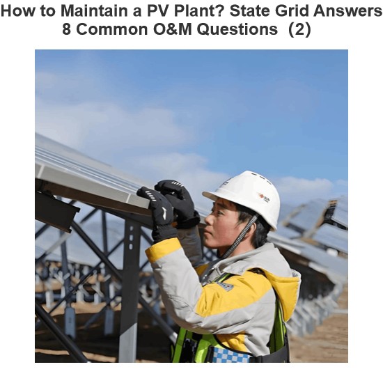
How to Maintain a PV Plant? State Grid Answers 8 Common O&M Questions(2)
1. On a scorching sunny day, do damaged vulnerable components need to be replaced immediately?Immediate replacement is not recommended. If replacement is necessary, it is advisable to do so in the early morning or late afternoon. You should contact the power station’s operation and maintenance (O&M) personnel promptly, and have professional staff go to the site for replacement.2. To prevent photovoltaic (PV) modules from being hit by heavy objects, can wire mesh protective screens be install
Encyclopedia
09/06/2025
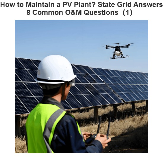
How to Maintain a PV Plant? State Grid Answers 8 Common O&M Questions(1)
1. What are the common faults of distributed photovoltaic (PV) power generation systems? What typical problems may occur in various components of the system?Common faults include inverters failing to operate or start due to voltage not reaching the startup set value, and low power generation caused by issues with PV modules or inverters. Typical problems that may occur in system components are burnout of junction boxes and local burnout of PV modules.2. How to handle common faults of distributed
Leon
09/06/2025
Short Circuit vs. Overload: Understanding the Differences and How to Protect Your Power System
One of the main differences between a short circuit and an overload is that a short circuit occurs due to a fault between conductors (line-to-line) or between a conductor and earth (line-to-ground), whereas an overload refers to a situation where equipment draws more current than its rated capacity from the power supply.Other key differences between the two are explained in the comparison chart below.The term "overload" typically refers to a condition in a circuit or connected device. A circuit
Edwiin
08/28/2025
Send inquiry
Download
Get the IEE Business Application
Use the IEE-Business app to find equipment, obtain solutions, connect with experts, and participate in industry collaboration anytime, anywhere—fully supporting the development of your power projects and business.