
Definition
A travelling wave is a transient wave that creates a disturbance and propagates along a transmission line at a constant speed. This type of wave exists for a short period (lasting only a few microseconds), yet it can cause significant disturbances in the transmission line. Transient waves are generated in the transmission line mainly due to operations like switching, faults, and lightning strikes.
Significance of Travelling Waves
Travelling waves play a crucial role in determining the voltages and currents at various points within the power system. Additionally, they are instrumental in the design of insulators, protective devices, insulation for terminal equipment, and overall insulation coordination in the power system.
Specifications of Travelling Waves
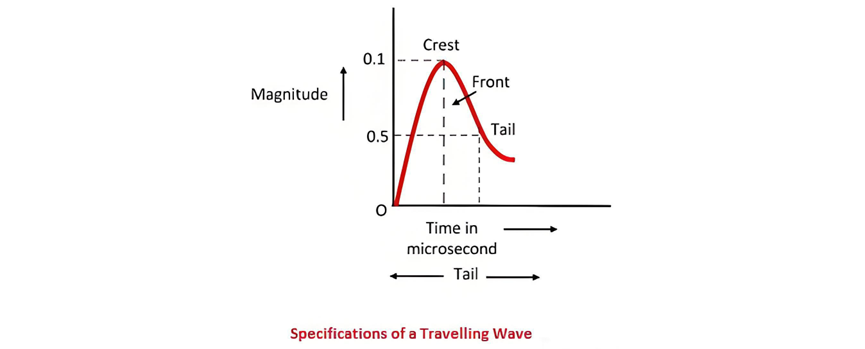
Mathematically, a travelling wave can be represented in multiple ways. It is most commonly depicted in the form of an infinite rectangular wave or a step wave. A travelling wave is characterized by four specific attributes, as illustrated in the figure below.
Characteristics of Travelling Waves
Crest: This represents the maximum amplitude of the wave and is typically measured in kilovolts (kV) for voltage waves or kiloamperes (kA) for current waves.
Front: It refers to the part of the wave that precedes the crest. The duration of the front is measured as the time interval from the start of the wave to the moment it reaches its crest value, usually expressed in milliseconds (ms) or microseconds (µs).
Tail: The tail of the wave encompasses the portion that comes after the crest. It is defined by the time elapsed from the start of the wave until the wave's amplitude decreases to 50% of its crest value.
Polarity: This indicates the polarity of the crest voltage along with its numerical value. For example, a positive wave with a crest voltage of 500 kV, a front duration of 1 µs, and a tail duration of 25 µs would be denoted as +500/1.0/25.0.
Surges
A surge is a specific type of travelling wave that arises from the movement of electric charges along a conductor. Surges are characterized by a very rapid and steep increase in voltage (the steep front), followed by a more gradual decrease in voltage (the surge tail). When these surges reach terminal equipment such as cable boxes, transformers, or switchgear, they can potentially cause damage if the equipment is not adequately protected.
Travelling Waves on Transmission Lines
A transmission line is a distributed - parameter circuit, which means it supports the propagation of voltage and current waves. In a circuit with distributed parameters, the electromagnetic field propagates at a finite velocity. Operations such as switching and events like lightning strikes do not affect all points of the circuit simultaneously. Instead, their effects spread across the circuit in the form of travelling waves and surges.
When a transmission line is suddenly connected to a voltage source by closing a switch, the entire line does not become energized instantaneously. In other words, the voltage does not appear immediately at the far end of the line. This phenomenon occurs due to the presence of distributed constants, namely inductance (L) and capacitance (C) in a loss - free line.
Consider a long transmission line with distributed - parameter inductance (L) and capacitance (C). As depicted in the figure below, this long line can be conceptually divided into smaller sections. Here, S represents the switch used to initiate or terminate surges during switching operations. When the switch is closed, inductance L1 initially acts as an open circuit, while capacitance C1 acts as a short circuit. At that very moment, the voltage at the subsequent section cannot change because the voltage across capacitor C1 is initially zero.
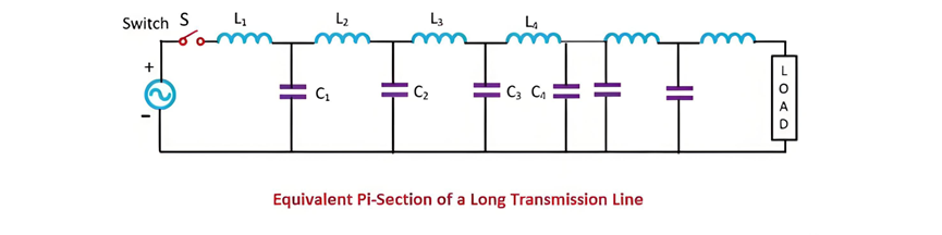
Therefore, until capacitor C1 is charged to a certain level, it is impossible to charge capacitor C2 through inductor L2, and this charging process inevitably takes time. The same principle applies to the third, fourth, and subsequent sections of the transmission line. As a result, the voltage at each section gradually increases. This gradual buildup of voltage along the transmission conductor can be visualized as a voltage wave propagating from one end of the line to the other. The associated current wave is responsible for this gradual charging process.The current wave, which travels in tandem with the voltage wave, generates a magnetic field in the surrounding space. When these waves reach junctions and terminations within the electrical network, they undergo reflection and refraction. In a network with numerous lines and junctions, a single incident wave can initiate multiple travelling waves. As the waves split and undergo multiple reflections, the number of waves increases significantly. However, it's important to note that the total energy of the resultant waves can never exceed the energy of the original incident wave, adhering to the fundamental law of energy conservation in electrical systems.


